Should I replace the TO-92s? I would need to desolder them from the board to test them anyways.
They are:
2SC904 x2
2SA569 x2
2SC871 x2
2SC711A x2
There will be modern equivalents and I probably already have some in my stash. I found a reference to the 2SC870/871 and 2SA569 being known to deteriorate with age, so I suppose I might as well replace them. I shall have to study suitable replacement parts.
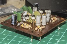
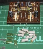
I've started work on recapping the small board which I take to be the preamp.
There are four transistors that I can't identify, they have gold legs and black and white plastic, with the following text: CDC 25100-6 108
The number 108 makes me think they could be BC108s but those are a European transistor which seems out of place in a Japanese built amp that uses Japanese transistors elsewhere.
Attachments
After a bit of research I've ordered some transistors to replace the TO-92 ones. Philips 2SC1815GR to replace the 2SC871 and 2SC711, NEC 2SA1175 to replace the 2SA569 and NEC 2SC2235 to replace the 2SC904.
I've had to order some 10uF and 4.7uF electrolytic caps, I'm wondering if I should also replace the green poly caps (Yamato brand) and the diodes - there are four tiny Zener diodes on the main board and three or four Schottky diodes in the point to point wiring of the power supply.
I've had to order some 10uF and 4.7uF electrolytic caps, I'm wondering if I should also replace the green poly caps (Yamato brand) and the diodes - there are four tiny Zener diodes on the main board and three or four Schottky diodes in the point to point wiring of the power supply.
I went ahead and replaced the green poly caps, might as well, I had all the correct values in my stash.
I still need to identify the transistors on this board, they have CDC 25100-6 108 written on them. Anybody?

I still need to identify the transistors on this board, they have CDC 25100-6 108 written on them. Anybody?
I have figured out that they are Siliconix manufactured JFETs, model J108.
I doubt I will be able to find NOS J108s, so I wonder what JFET that is available would be a suitable replacement?
Or maybe I should just leave the originals in place?
I doubt I will be able to find NOS J108s, so I wonder what JFET that is available would be a suitable replacement?
Or maybe I should just leave the originals in place?
They 100% are not jfets conventional NPN bipolars at this time a j fet would be a rare exotic item just do the diode type test with a multimeter
Trev
Trev
JFETs weren't rare or exotic by the time this amp was built. For example, here's a list of low cost JFETs from a 1969 magazine article:
JFETS: How They Work, How to Use Them, May 1969 Radio-Electronics - RF Cafe
An externally hosted image should be here but it was not working when we last tested it.
JFETS: How They Work, How to Use Them, May 1969 Radio-Electronics - RF Cafe
They were only a dollar in single quantity so probably half that in the quantities a manufacturer would buy, which doesn't preclude their use in this amp.
No, I haven't tested them, that would mean de-soldering one from the board, which I'm not keen to do as I don't have a schematic and fear getting the placement of the legs wrong.
No, I haven't tested them, that would mean de-soldering one from the board, which I'm not keen to do as I don't have a schematic and fear getting the placement of the legs wrong.
The transistors are probably made by Micro Electronics Ltd. 美科有限公司- Home Page as in the early Sinclair amplifiers. ( ceramic base, epoxy dome ).
Sinclair Radionics - an inside view. Part 2.
Andy
Sinclair Radionics - an inside view. Part 2.
Andy
#30 "The small signal ones were ceramic TO18 transistors. The chip was on a ceramic base through which the lead wires fed loosely. An epoxy cover was then put over the whole, holding the leads firm and the whole together.
At least, that was the theory. In practise the leads were not always properly held in the ceramic and the act of spreading them to fit the board would sometimes break them loose. And a slight sideways pressure on a transistor would sometimes be enough to break the ceramic-epoxy bond: a lead would then push upwards and the top of the transistor would pop off. This of course caused problems in production and breakages in transit, and in the customer's hands!"
You only need to know the pinout and type (npn or pnp). Replacement for small signal BJT GP. If it works, don't hurry🙁
Last edited:
I think I'll try the amp with these original transistors still in place, if it doesn't work, then I can look into changing them. I just see too many opportunities to make a mess of things, so unless they turn out to be a problem, I'll leave them be.
I truly hope that you do progress your amplifier for me they have a special place in history !For the aspirational working man it was a significant upgrade from a dansette or a radio gram !
Tha amplifier while being budget was in some ways a little miracle Talking to the rep Ray Collins he told me the landed price (At the docK) was about £8 So think about this shipped half way around the world Wholesalers profit retailers profit Gov tax
Indeed a little miracle
Also very early use of plastic power devices
Trev
Cheers Trev.
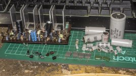
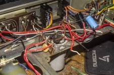
I've replaced all the transistors (apart from the four E108 JFETs on the preamp) and caps, then I found a broken resistor, and wouldn't you know it, I don't have any 220ohm ones in my stash to replace it, so I've ordered some.
Once I've replaced the resistor I'll put it back together and see if it works. I suspect this resistor is why one channel wasn't working.
Attachments

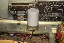
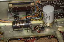
Here's how I replaced the large ELNA 35v 2200uF smoothing cap, the BHC 40v 2200uF I had was a bit smaller so wouldn't fit in the original mount. I just cut off the metal tabs on the ELNA so all the wiring connected to them stayed untouched, then soldered a couple of thick pieces of solid copper wire to the tabs and soldered the other ends to the new cap.
Anyone see any issues with the way I've done this?
I happen to have one more of these BHC 40v 2200uF caps, would adding it in parallel improve the smoothing?
Anyone see any issues with the way I've done this?
I happen to have one more of these BHC 40v 2200uF caps, would adding it in parallel improve the smoothing?
Attachments
I used a blob of glue to hold the cap in place, I don't think the wiring can move enough to short anything, but I'll double check.
ian It looks like you have been busy ! I cannot wait until you are in a posistion to power it up. Will you bee using a test lamp set up i.e. a series connected 40 watt lamp so as to minimise any fault currents rather than just giving it full power
Keep up the commentary as i am enjoying it
Trev
Keep up the commentary as i am enjoying it
Trev
I figured I'd try a pair of headphones first, then if that works, hook up some speakers.
I'm just waiting for the required replacement resistor to arrive in the post then I can put it back together, with fingers crossed I replaced everything correctly. I did my best to make sure I got all the transistors the right way round. The new ones have the opposite pinout of the old ones so I made sure to place them the opposite way round, I just hope I got it right as I don't have a schematic to work from.
I'm just waiting for the required replacement resistor to arrive in the post then I can put it back together, with fingers crossed I replaced everything correctly. I did my best to make sure I got all the transistors the right way round. The new ones have the opposite pinout of the old ones so I made sure to place them the opposite way round, I just hope I got it right as I don't have a schematic to work from.
It likely would but if you want to get something working again without instruments that show you all the effects of each change, try to minimise the number of changes made at each step. So unless there is some compelling reason, avoid the complication of "upgrading" parts on the fly. It's a convenient time to mod things but it may have no relevance to what you're working on and changing more than one variable at a time can easily end up in losing the repair plot........I happen to have one more of these BHC 40v 2200uF caps, would adding it in parallel improve the smoothing?
When it's working properly is the time to tinker about with parts values because only then can you be certain whether such changes really do anything worthwhile or even make it sound worse.
- Home
- Amplifiers
- Solid State
- 1971 Highgate Acoustics Alpha FA-200