Thanks Mark, this is good knowledge..
John, thank you for posting the test results...
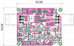
my latest layout pic is here, with corrections as mentioned by you...including C4 correction
Layout is a bit tight, but doable with careful soldering plan..
John, thank you for posting the test results...
my latest layout pic is here, with corrections as mentioned by you...including C4 correction
Layout is a bit tight, but doable with careful soldering plan..
Attachments

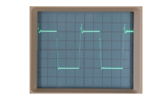
If I had an AP analyser I would also use 20kHz to measure the distortion. With the old analyser I have, I set it to 100kHz bandwidth. Which means I can measure up to 4th harmonic of 25kHz. That will be slightly more sensitive to distortion as the loop gain will be a little less than at 20kHz.
The bandwidth in the display is the narrow band used to measure individual frequency ranges between the set limits (here 10kHz-110kHz). I could get a finer frequency resolution using a narrower bandwidth but the measurement time would extend.
Regarding the "50kHz" image the timebase on the scope is 5us/div. That makes it about 62kHz.
I really should make a front panel scale for my oscillator.
If I had an AP analyser I would also use 20kHz to measure the distortion. With the old analyser I have, I set it to 100kHz bandwidth. Which means I can measure up to 4th harmonic of 25kHz. That will be slightly more sensitive to distortion as the loop gain will be a little less than at 20kHz.
The bandwidth in the display is the narrow band used to measure individual frequency ranges between the set limits (here 10kHz-110kHz). I could get a finer frequency resolution using a narrower bandwidth but the measurement time would extend.
Regarding the "50kHz" image the timebase on the scope is 5us/div. That makes it about 62kHz.
I really should make a front panel scale for my oscillator.
Have you tested the amplifier on square wave input at 10kHz with a low value capacitor in parallel with the load. I have updated my .asc file and the prediction with as little as 10n was not pretty.
...Where did I goof ?...
What "goof"?
Your sim makes perfect sense. Biased at 0.5A you can get near 1A 8V peak in class A, and push into class AB to about 20V 2.5A peak. With the large 0.5A idle current there will be little change in THD as you transition A to AB.
mjona - I do not see instabilities in my simulations using 2SC5200 output transistors with 100nF capacitive load, but there is a slight overshoot on leading edge. I do see oscillations with TIP3055.
I'll measure the actual amplifier tomorrow.
I'll measure the actual amplifier tomorrow.
What "goof"?
Your sim makes perfect sense. Biased at 0.5A you can get near 1A 8V peak in class A, and push into class AB to about 20V 2.5A peak. With the large 0.5A idle current there will be little change in THD as you transition A to AB.
Thank you dear PRR. It will be a good candidate for assembly ! Shall wait for final tweaks from John !
mjona - I do not see instabilities in my simulations using 2SC5200 output transistors with 100nF capacitive load, but there is a slight overshoot on leading edge. I do see oscillations with TIP3055.
I'll measure the actual amplifier tomorrow.
The characteristics of the speaker cable are not included in the simulation. If you have a small overshoot it could be the simulation is wrong or the cable plays some part in the cause of stability. I did not see any output coil.
I persevered with the simulation re the residual overshoot. In this your input low pass filter does practically nothing to spoil the square wave shape. You could increase the value of the capacitor in the filter to see if you can get rid of the overshoot.
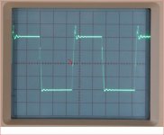
Here is an image of an approximately 10kHz square wave with a 1uF capacitor load directly taken from the output pin, while the 7.5 ohm dummy load is also connected via a twisted pair cable. (5V/div vertical which keeps the slight overshoot from clipping).
It is not the cleanest waveform but it is not unstable, either.
I would urge anyone with capacitive loads to include the usual LR parallel network in series with the load. I've simulated with a 3.3uH/1 ohm pair and that seems to suppress oscillations even with a TIP3055 output pair.
It is not the cleanest waveform but it is not unstable, either.
I would urge anyone with capacitive loads to include the usual LR parallel network in series with the load. I've simulated with a 3.3uH/1 ohm pair and that seems to suppress oscillations even with a TIP3055 output pair.
Attachments
Last edited:
On the overshoot
The shot shows a two stage progression in the angles of the rising slope with the nexus of two lines indicated in the attachment. This has to be the limit of your capability with 1uF in your test.
It would be interesting to work out the peak frequency corresponding to the rise time to the nexus.
If this was say 3uS that would equate to 333kHz pulsing momentarily into a 1 uF capacitor reactance of a fraction of an Ohm in parallel with 8 Ohms.
Unlike Class B amplifiers this one has a limited current delivery capability with clear implications on the cause of the overshoot.
Linsley-Hood was apt to use 2uF parallel test loads but he used passive low pass input filtering to limit the input frequencies to about 50kHz - his designs would work with electrostatic speakers which present difficult loads.
That looks extreme for general use so a low pass input filter with a higher cut off frequency than 50kHz may still keep the demands of the input stage of your amplifier within the slew rate capacity.
By juggling values for a low pass input filter and lower test capacitor values, to avoid limiting of slew rate and current clipping, a lower value output coil might suffice.
Here is an image of an approximately 10kHz square wave with a 1uF capacitor load directly taken from the output pin, while the 7.5 ohm dummy load is also connected via a twisted pair cable. (5V/div vertical which keeps the slight overshoot from clipping).
It is not the cleanest waveform but it is not unstable, either.
I would urge anyone with capacitive loads to include the usual LR parallel network in series with the load. I've simulated with a 3.3uH/1 ohm pair and that seems to suppress oscillations even with a TIP3055 output pair.
The shot shows a two stage progression in the angles of the rising slope with the nexus of two lines indicated in the attachment. This has to be the limit of your capability with 1uF in your test.
It would be interesting to work out the peak frequency corresponding to the rise time to the nexus.
If this was say 3uS that would equate to 333kHz pulsing momentarily into a 1 uF capacitor reactance of a fraction of an Ohm in parallel with 8 Ohms.
Unlike Class B amplifiers this one has a limited current delivery capability with clear implications on the cause of the overshoot.
Linsley-Hood was apt to use 2uF parallel test loads but he used passive low pass input filtering to limit the input frequencies to about 50kHz - his designs would work with electrostatic speakers which present difficult loads.
That looks extreme for general use so a low pass input filter with a higher cut off frequency than 50kHz may still keep the demands of the input stage of your amplifier within the slew rate capacity.
By juggling values for a low pass input filter and lower test capacitor values, to avoid limiting of slew rate and current clipping, a lower value output coil might suffice.
Attachments
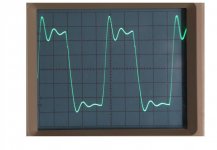
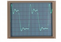
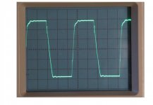
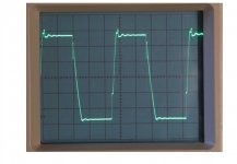
I would like to thank mjona for his assistance. I have now tested the circuit with some input and output filter combinations. In the attached images I have the approx. 10kHz square wave input with 2.2uF load (in parallel with 7.5 ohm) without filters; a 2.2uF load with 50kHz input filter (3.3k/1nF); a 2.2uF load with input filter and 2.5uH//4.7 ohm LR output filter and 2.2uF load with output LR only.
None of these have eliminated the approx. 1MHz inversions in the leading and trailing edges, so there is a little more work to be done to eliminate those, but the circuit is essentially able to handle capacitive loads.
I recall Doug Self commenting that it was "cruel" to load a VAS stage with a resistor. I have to say that loading an amplifier with a capacitor is even more so.
The problem is all related to slew rate. To drive a 2.2uF load at 20kHz and 16W requires a peak current of 4.4A, plus the current in the 8 ohm load, which will have an effect on the overall impedance (you cannot just add the 8 ohm load current). Since the current in a capacitor is out of phase with the input, at the start of what might be called a 20kHz "sinewave pulse" or signal, the amplifier has to shift almost instantly from delivering 0A to 4.4+ A.
This design is not able to deliver such a current unless the quiescent current is increased to 2.2A (minimum), and even then will be slew rate limited.
This problem is not cured by using a 50kHz input filter, so I have to say that JLH's original class A design would also have the same slew rate problem at 20kHz, so while his design may have been stable with a 2.2uF load it could have suffered from slew induced distortion if signals of 20kHz or over were present in the input, although his 10W circuit would only need a quiescent current of about 1.75A.
Even with a 2.2A quiescent current, with a static dissipation approaching 100W, which would need a rather excessive heatsink, there is no margin at higher frequencies, were these to be present. I would advise against using electrostatic speakers or load capacitors.
Since the LR filter is more effective in this case at reducing the high frequency inversion I suggest that a filter is used even with an ordinary speaker.
To guarantee avoiding slew rate limiting, a Zobel network would have to restrict the load impedance to that which the amplifier can handle. Most LR filters are not true Zobels - Zobel's intention was to present a constant impedance. To balance 2.2uF at 8 ohms at 20kHz an inductance of around 63uH is needed, which I think most users would notice impacting the bandwidth unnecessarily, as well as causing a response peak unless suitably damped.
For capacitive loads it really does seem that a high power output stage operating in Class AB is more appropriate.
I can say that with the output LR network, the 16W design gives a clean square wave into a resistive load. This does seem to be worthwhile, and Prasi has kindly modified the PCB to accept an input RC filter, so if builders need to use a filter, a 1k to 3.3k with 1nF would be possible (150kHz-50kHz).
Now to investigate that glitch.
Attachments
Not really.
The amplifier prototypes both worked well (my original and one based on Prasi's layout).
Following discussions with mjona I changed the compensation scheme a little.
The only real hint of trouble I found was a very slight tendency to oscillate during square wave testing, and then only during the transistions. That was caused by, as was discussed, slew limited stages. As that changed the stability one cure was to add a couple of diodes to limit the internal overdrive during the fast edges. They should have been included anyway as a matter of precaution against reverse biasing the VAS stage base junctions.
Probably still needs more work.
Updates shown attached.
Attachments

Last edited:
- Home
- Amplifiers
- Solid State
- 16W Class A - inspired by JLH