I built a standard test board with a TDA1541A and NE5534 I/V, driven by an ESP8266-based I2S generator. Now I can send any test signal to the test board. I generated a 6-bit dithered 😉 pure sine (-60 dB) and measured the output spectrum. What I observed is that the distortion depends on the upper bit values. Ex.: 0x7FFF FFFF FFxx xxxx is higher than 0x0000 0000 7Fxx xxxx etc. The best distortion I measured is below 0.1%, the worst is 0.28%, depending on the digital shift. The digital shift will cause analog DC shift after conversion. Transition between 0x7FFF FFFF FFFF FFFF to 0x8000 0000 0000 0000 is the analog zero, with 0.28% THD. But I found a method to reduce it 🙂.
Aha, so music miss something 😉great sound have price , this is why numbers doesn't and never made music by themself
//
Some little upgrade to my setup lead to an improvement of the Thd+N at -60 dB fs , and fact it is audible on some records :

.
.
Last edited:
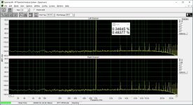
Here is my -60 dBFS. The difference is the sampling rate in my setup is 48 kHz and I used dithered sine. Hence the -130 dB noise floor compared to your -150 dB. I measured THD, not THD+N. Otherwise my THD is very similar to yours. The spectrum lines match more or less.
One can get 0.2% on a good day, but 0.4% to 0.5% is more common.
One can get 0.2% on a good day, but 0.4% to 0.5% is more common.
Attachments
Do you use your DNL setup on these graph ?
my numbers are limited by the trafos ( sowters 1495 ) at the output I think I am arrived at their limits
and I am about to consider adding you DNL trick at an new pcb I am working on
.
my numbers are limited by the trafos ( sowters 1495 ) at the output I think I am arrived at their limits
and I am about to consider adding you DNL trick at an new pcb I am working on
.
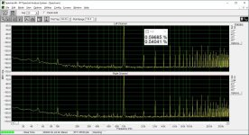
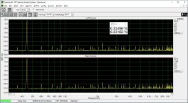
However I prefer testing at 440 Hz -60 dBFS dithered sine. It takes more sampling cycles for one signal period, it is closer to musical tones, and gives better THD results 😉. The dither is +/-1LSB triangular probability function random noise.
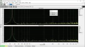
THD 0dBFS is also attached, signal is attenuated by 20 dB.
THD 0dBFS is also attached, signal is attenuated by 20 dB.
Attachments
- Home
- Source & Line
- Digital Line Level
- 16 bit DAC AT-60DB