
Hello Kadimba
greetings is it possible to post SPRINT lay file of NX300
i want to use big die IRFP4227
warm regards
Andrew
greetings is it possible to post SPRINT lay file of NX300
i want to use big die IRFP4227
warm regards
Andrew
Do someone here have the N10 Amplifier PCB first posted here, Basically the Thread started to diy this amp.
Go to N20
Thank you very much for your reply and suggestion, I tried the BUZ Amp with IRFP250 with +/- 45v and after few seconds got the Magic smoke,😱 Might be Oscillating Amp.
so want to complete the Amp with fewer components N10, so if PCB is available please do provide me.
so want to complete the Amp with fewer components N10, so if PCB is available please do provide me.
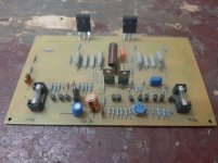
Attachments
What exactly misfired?. Have you used BF870 or BF871. I think BF transistors appear fake. Are BF transistors ok after the smoke.
Got the old BF870 and 869 from known source originals... They worked well quite a long back when tried with IRF150 T03 metal package.😕
No my question was did BF869 still alive after smoke. If they are dead then it must have destroyed MOSFET as well. I had assembled Elektor HITACHI BUZ23 mosfet amplifier long back with BC556 and BC546 only with a rail voltage of 25-0-25V DC and it worked very well. However I did not try with BF870 as I could not get it in the market. I am still in search of NOS Philips BF469/470 and BF869/870. Thanks
I worked for IR for close to 2 decades. IN the fab, which is where semiconductors are manufactured.
I Personally would Not Use IRF parts. I have reasons which I won't go into here, but I was 'in the trenches' for a long time and we could not, IMO, turn the corner on quality......
I Personally would Not Use IRF parts. I have reasons which I won't go into here, but I was 'in the trenches' for a long time and we could not, IMO, turn the corner on quality......
Human ears cant hear THD<1%
Well I have to disabuse you, I can detect 3rd harmonic of a 200Hz tone at 57dB down, if its turned on and off. That's 0.14%, and my ears are a lot older than they used to be.
When it comes to intermodulation products (which appear at non-harmonically related frequencies) I'd expect some distortion products will be audible down to -70dB or lower, especially when the intermodulating tones are at the HF end of the spectrum.
I worked for IR for close to 2 decades. IN the fab, which is where semiconductors are manufactured.
I Personally would Not Use IRF parts. I have reasons which I won't go into here, but I was 'in the trenches' for a long time and we could not, IMO, turn the corner on quality......
I have used IRF240/9240 in amps for about 15 years now.
Never had any problems with them. If the amp is tamed properly it usually behaves.
I have had trouble with fake/copy parts though. One set lasted 10 minutes until I unplugged my soldering iron. The glitch on mains killed them.
Bought in some genuine parts from RS Components and they are still going years later.
15 years, eh? I was probably process tech in the fab for those years.....
maybe until 2010 or so when I reached my limit.
Our scrap rate was too high. And that was taking 100 x 6" slices of epitaxial Silicon and putting 'em right in the trash....after misprocess.....
Any idea what a SINGLE wafer such as I describe would cost?
I worked on BOTH process AND product improvement activities.
Mr Arasuk,
You seem to me from Bangalore. My advice is make Elvee's Circlophone. It's an eccellent amplifier with no adjustments. Very good operation between Class A and Class AB, works very well with 2N3055. I made it and I am extremely happy with the prototype. I now intend to make 2 sets more for a stereo setup. I am also trying to assemble its Mosfet version too.
You seem to me from Bangalore. My advice is make Elvee's Circlophone. It's an eccellent amplifier with no adjustments. Very good operation between Class A and Class AB, works very well with 2N3055. I made it and I am extremely happy with the prototype. I now intend to make 2 sets more for a stereo setup. I am also trying to assemble its Mosfet version too.
Hi all.
Its been a while since I bult anything. Regardless, I have built the NX14, and would like to finish it soon. regarding the biasing, post 74 says to put 10ohm resistors in place of the fuses, but where do i connect the multimeter? Do I put to a10r resistor in each fuse holder and how much watts must it be? Then how or where do I connect the multimeter to measure the bias? and what is he best bias setting for the NX14. Please help
Its been a while since I bult anything. Regardless, I have built the NX14, and would like to finish it soon. regarding the biasing, post 74 says to put 10ohm resistors in place of the fuses, but where do i connect the multimeter? Do I put to a10r resistor in each fuse holder and how much watts must it be? Then how or where do I connect the multimeter to measure the bias? and what is he best bias setting for the NX14. Please help
Hi all.
Its been a while since I bult anything. Regardless, I have built the NX14, and would like to finish it soon. regarding the biasing, post 74 says to put 10ohm resistors in place of the fuses, but where do i connect the multimeter? Do I put to a10r resistor in each fuse holder and how much watts must it be? Then how or where do I connect the multimeter to measure the bias? and what is he best bias setting for the NX14. Please help
If you don't like magic smoke put an incandescent lamp in series with the transformer primary side. This will limit current in case of troubles.
You can use those protect 10R resistors instead of fuses simultaneously.
The multimeter need to measure the voltage across 10R.Use the ohm's lay to find the current. I=V/R. Where R=10R.
This will be the total current,not the bias.
Under normal conditions you must see the incandescent lamb to glow instantly and then dim.If you see full glow, remove the main voltage, disconnect the 220V connection.Discharge caps in power supply.Look for wrong placed transistors e.t.c...e.t.c.
Across 10R a voltage measurement about 1.5-2V will expected.In this case, I=1.5/10. This is 0.15A or 150mA.
If it is something >200mA you must lower current using bias trimmer.
If all these are without magic smoke measure output with a voltmeter. Use d.c scale. One lead at the output and the other at the gnd.
You MUST see something up to 100mV.
If it is larger than 100mV disconnect everything and inspect.. Everything!
If you successfully pass the test, disconnect the incandescent lab, close the circuit (direct connect main voltage at the transformer primary side, keep the 10R resistors in place and repeat the test.
If you successfully pass this test, remove 10R,put the fuses and go for the second procedure, the bias adjustment.
Measure d.c voltage across R26 resistor 0.1ohm.
Don't remember what is the recommended bias but 50mA will be fine for the first test. Use the ohm's lay I=V/R.
Keep the input sorted during all test. Use a jumper between input + and gnd.
For 50mA bias you expect 0.005 V across R26.
So I=0.005/0.1=0.05A or 50mA.
Depending of your heatshings size you can use bigger bias.I think up to 200mA.
Last edited:

Go to N20
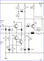
Sir Mile can i use this Protect from AX14 to FH9 Sir thank you so juch sir
Attachments
- Home
- Amplifiers
- Solid State
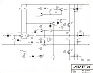
- 150W MOSFET Amplifier with IRFP250x2