Best to peal the plastic and use some thick paper isolation, so the sound gets back again.
Did this with my Cary SLM-100 (they use 2 stacked caps for the main and 2 for driver).
1. Original with about 10 years old cap: At first without the tweak, sound not so nice
2. Pealed the plastic than 😱
3. Replaced with new caps. Same ugly sound went back
4. Pealed again and put thick paper isolation, while the Alu cap may connected, needs isolation to the ground.
5. finally back with nicer sound (is unbelievable to basic electronic terms)
Then did it on all my gear.
actually caps with the black or colored plastic wrappers can dissipate heat better than when bare.....
I dont have a formal capacitor reformer. And I'm not comfortable about just strapping up something by the seat of my pants on the breadboard to do a reform of many capacitors. So I was thinking of building this little guy from Popular Electronics October 1970 page 46. It has slow reforming and slow discharging capabilities. I suppose the circuit can be improved by adding an ammeter and voltmeter of what is actually at the cap terminals at any time. What do you think? I have all the parts already I'm sure. the lowest voltage is 100V the highest 600V but I suppose I can slide that whole divider down to be 25V through 500V since my personal self-imposed limit in this hobby I've set at 450V, maybe someday when I'm better I'll up that number.
In doing this I would probably put each capacitor under an inverted plastic household bucket, just in case.
Build an Electrolytic Restorer, October 1970 Popular Electronics - RF Cafe
In doing this I would probably put each capacitor under an inverted plastic household bucket, just in case.
Build an Electrolytic Restorer, October 1970 Popular Electronics - RF Cafe
Last edited:
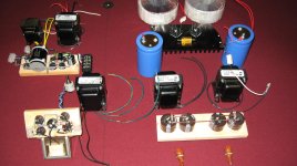
9100uF on 6C33C B+
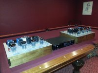
FWIW, I also use the big blue computer caps on B+. Each B+ on my 6C33C OTL mono's have a CLC supply. The first cap is a 4700uF bule can. The second is a pair of 2200 snap ins. The amps sound great. Fast, natural and uncolored. Each mono has about 20000uf total caps in the PS.
FWIW, I also use the big blue computer caps on B+. Each B+ on my 6C33C OTL mono's have a CLC supply. The first cap is a 4700uF bule can. The second is a pair of 2200 snap ins. The amps sound great. Fast, natural and uncolored. Each mono has about 20000uf total caps in the PS.
Attachments
Last edited:
I dont have a formal capacitor reformer. And I'm not comfortable about just strapping up something by the seat of my pants on the breadboard to do a reform of many capacitors. So I was thinking of building this little guy from Popular Electronics October 1970 page 46. It has slow reforming and slow discharging capabilities. I suppose the circuit can be improved by adding an ammeter and voltmeter of what is actually at the cap terminals at any time. What do you think? I have all the parts already I'm sure. the lowest voltage is 100V the highest 600V but I suppose I can slide that whole divider down to be 25V through 500V since my personal self-imposed limit in this hobby I've set at 450V, maybe someday when I'm better I'll up that number.
In doing this I would probably put each capacitor under an inverted plastic household bucket, just in case.
Build an Electrolytic Restorer, October 1970 Popular Electronics - RF Cafe
this is how i do it....
say i have a 100vdc cap to reform, so then i will get a dc supply with 150vdc terminal voltage, so if i want to limit the current to 2mA in case of a leaky cap, i will choose a resistor of 150/2mA or 75k, 5 watt resistor...
now, when the cap has reformed to 100vdc, the leakage current would then be, (150 - 100)/75k = 0.67 mA a very good number...
Absolutely!! Good eye!I'll bet you got those power transformers from A1 🙂
I use them in my monoblocs, too.
Picked up 4 x 572VA at $20 each. Made for a stiff but cost effective PS with two per mono. One each on push and pull.
The Blue computer caps also surplus from A1 at $10 ea. Reformed quick and clean and work like a charm.
Last edited:
you may even find that the cap under test can reform to more than 100vdc, do not be afraid, as long as the leakage current is very low that is not a problem....
in general, the trend is for the leakage current to diminish with time...
btw, higher voltage caps will probably take more hours to form than lower voltage caps..
but as a caveat, do not use the cap at the maximum rated volts as a good practice...
so that if you run that cap at say 85 vdc, then you can be secured in the knowledge that an increase in primary voltage, your cap will survive....
after reforming, discharge using a 220v 100 watt lamp, and then short the terminals to prevent charge build ups and preserve your cap till the time you are installing them...
Thanks Tony,
Knowing this and seeing that Popular Electronics project, I can do better in making a cap reformer. The project in the article is mostly a power supply with a relatively inaccurate and course voltage selector switch. Since I already have a Heathkit bench supply for tubes with an accurate pot for voltage selection. I can make my cap reformer where you just give it that supply. Then only incorporate the slow, medium, fast resistors and the discharge switch, and add some digital meters. My circuit would assume the supply is from your bench supply IOW and accurate. And it would have the leakage and voltage meters all built in with current sense shunts, supply voltage and current voltage across the capacitor. I could even add a timer relay so one could "cook" a capacitor for a pre set time and it will automatically shut off, because humans forget to shut off devices like this and might leave a capacitor reforming for a week. With an Arduino I suppose you can even have it detect when the target leakage number is reached? Then have it shut off and discharge ahead of the timer.
Knowing this and seeing that Popular Electronics project, I can do better in making a cap reformer. The project in the article is mostly a power supply with a relatively inaccurate and course voltage selector switch. Since I already have a Heathkit bench supply for tubes with an accurate pot for voltage selection. I can make my cap reformer where you just give it that supply. Then only incorporate the slow, medium, fast resistors and the discharge switch, and add some digital meters. My circuit would assume the supply is from your bench supply IOW and accurate. And it would have the leakage and voltage meters all built in with current sense shunts, supply voltage and current voltage across the capacitor. I could even add a timer relay so one could "cook" a capacitor for a pre set time and it will automatically shut off, because humans forget to shut off devices like this and might leave a capacitor reforming for a week. With an Arduino I suppose you can even have it detect when the target leakage number is reached? Then have it shut off and discharge ahead of the timer.
Last edited:
Thanks Tony,
Knowing this and seeing that Popular Electronics project, I can do better in making a cap reformer. The project in the article is mostly a power supply with a relatively inaccurate and course voltage selector switch. Since I already have a Heathkit bench supply for tubes with an accurate pot for voltage selection. I can make my cap reformer where you just give it that supply. Then only incorporate the slow, medium, fast resistors and the discharge switch, and add some digital meters. My circuit would assume the supply is from your bench supply IOW and accurate. And it would have the leakage and voltage meters all built in with current sense shunts, supply voltage and current voltage across the capacitor. I could even add a timer relay so one could "cook" a capacitor for a pre set time and it will automatically shut off, because humans forget to shut off devices like this.
Knowing this and seeing that Popular Electronics project, I can do better in making a cap reformer. The project in the article is mostly a power supply with a relatively inaccurate and course voltage selector switch. Since I already have a Heathkit bench supply for tubes with an accurate pot for voltage selection. I can make my cap reformer where you just give it that supply. Then only incorporate the slow, medium, fast resistors and the discharge switch, and add some digital meters. My circuit would assume the supply is from your bench supply IOW and accurate. And it would have the leakage and voltage meters all built in with current sense shunts, supply voltage and current voltage across the capacitor. I could even add a timer relay so one could "cook" a capacitor for a pre set time and it will automatically shut off, because humans forget to shut off devices like this.
TBH, I have no dedicated gear to do reforming, since i have a lot of power traffos lying around, i just pick one that suits my present need, it is not everyday that we do reforming, ymmv of course...
and you are free to do as you think is fit in your application...
and you are free to do as you think is fit in your application...
I have a bunch of Sprague can electrolytics harvested from a defunct Tek 535 oscilloscope, probably early ‘60’s. They have black cardboard tubes, and would look good on the top of the chassis.
Is there any likelihood they could be pushed into service again?
Is there any likelihood they could be pushed into service again?
Lol I dont think they're such a thing as an attractive capacitor.
I wouldn't think for one minute about using 60s electrolytics - you did see us talking about 90s capacitors
right?
Throw them away
I wouldn't think for one minute about using 60s electrolytics - you did see us talking about 90s capacitors
right?
Throw them away
I have a bunch of industrial 90's capacitors that I've rarely used (470 - 6800μF 350/450V). Anytime I've measured them, ESR has been around 20 - 60 mOhm (depending on size) and consistent (with the meter I have). Leakage less than a μA at low voltages (barely measurable with my 5 1/2 bench meter).
Would be good to have an easy way to test them at higher voltages, too. So instead of rigging up a transformer, rectifier etc. every time, I've been eyeing this 400V power supply from HSPY:
HSPY 400V 1A DC Bench Switch Power Supply Adjustable Laboratory Power Source Digital Professional voltage regulator 220 v|Switching Power Supply| - AliExpress
It seems to be available on Amazon, too. Someone on eevblog tore it down and reviewed it:
HSPY Power Supply - Page 1
Looks like the 400V variant is good quality. It is also incredibly small. So I have put it on my budget list of laboratory equipment.
A historical anecdote: These capacitors are BHC Aerowox. This was a UK company owned by US Aerowox. In 2002 it was aquired by Finnish Evox Rifa. In 2007 Evox Rifa was aquired by US company Kemet. So today you will find similar spec capacitors as the BHC ones with Kemet written on them.
Last edited:
Lol I dont think they're such a thing as an attractive capacitor.
What??? I would decorate with them if only the missus allowed it. 😀
- Home
- Amplifiers
- Tubes / Valves
- 1400 uf 350 VDC computer grade electrolytic