Is it alright to power that LM3875 chip with only 13v?
I just found a (BIG!) transformer from my old National XE550 equipment, though I haven't checked its output voltage yet. Loking at the label, the equipment can be powered by 13v worth of battery, so I assume that the transformer has an output voltage of 13v. The datasheet for the LM3875 states that the minimum voltage range is 20v. But, I think I've read here somewhere that someone has driven the chip below 20v. I just want to be sure. 🙂
I just found a (BIG!) transformer from my old National XE550 equipment, though I haven't checked its output voltage yet. Loking at the label, the equipment can be powered by 13v worth of battery, so I assume that the transformer has an output voltage of 13v. The datasheet for the LM3875 states that the minimum voltage range is 20v. But, I think I've read here somewhere that someone has driven the chip below 20v. I just want to be sure. 🙂
As long as you have high efficiency speakers, and possibly keep gain to the minimum to prevent clipping....
I'm a beginner in this stuff. 😱
So, I'm planning to use the speakers that came with the old national xe550 equipment. How do I know the speakers are of high efficiency? Only values found at the label are Impedance (6Ohms) and Peak Input (165W).
Thanks!
So, I'm planning to use the speakers that came with the old national xe550 equipment. How do I know the speakers are of high efficiency? Only values found at the label are Impedance (6Ohms) and Peak Input (165W).
Thanks!
Sensitivity is normally qouted in how many decibels you can create with 1 watt at a meter. I would say high efficiency designs would have figures of at least 90bd/W and hopeuflly more.... but this normaly comes at a sacrifice of power handleing with the exception of some PA equipment.
So I would bet your 160W speakers are not all that efficient.
I would say build the amp, give it a listrn with the tranny you have then get a proper one, you can even save a 10er or so a month, times speeds up as we age, and age we do. So in no time You can get what you need with some patience... I would save the tranny you have now for another project.
I have run LM3875 at with 11V trany for testing before, worked just fine. Sure it would not be a good idea to open up the volume...
13V may not work. The 20V in the datasheet is conservative but you may not be able to get down to 13. I have gotten as low as 16V on some LM3886 (very similar) but not lower.
Good luck,
---Troy
Good luck,
---Troy
I believe I read in the Lm3886 datasheet that it has some form of undervoltage protection which needs something like 11v to disable it ,so there is a Posibility that you can run it off of 13v...
Nordic said:
I would say build the amp, give it a listrn with the tranny you have then get a proper one, you can even save a 10er or so a month, times speeds up as we age, and age we do. So in no time You can get what you need with some patience... I would save the tranny you have now for another project.
I have run LM3875 at with 11V trany for testing before, worked just fine. Sure it would not be a good idea to open up the volume...
I"ll try the 13v transformer first, then if it wont work ( which I think is really going to happen
 ) then I guess I"ll have to save. Thanks for the replies everyone! 🙂
Just found out that the transformer has 4 wires for the secondaries. I dont know which is which but the 4 wires are being paired by 2. 2 wires are colored blue and has an output voltage of 16v while the other pair ( colored orange ) produces 27v. Got the voltage using my analog multitester. 😉
So, is this one alright to use for the LM3875 chip? Planning to use this for two LM3875 monoblocs.
So, is this one alright to use for the LM3875 chip? Planning to use this for two LM3875 monoblocs.
Assuming it can handle a few ampere it should be nice and even give you a nice supply for a buffer stage...
How can I know if it can handle "a few ampere"? How do I "calculate" for the transformer's VA?
Sorry for asking all this noobie questions. 😱
Sorry for asking all this noobie questions. 😱
Hi D,
what kind of transformer is it?
What size is it?
How heavy is it?
How thick are the copper leads? mains, 16V sec and 27V sec?
These will give us a clue or two.
what kind of transformer is it?
What size is it?
How heavy is it?
How thick are the copper leads? mains, 16V sec and 27V sec?
These will give us a clue or two.
AndrewT said:Hi D,
what kind of transformer is it?
What size is it?
How heavy is it?
How thick are the copper leads? mains, 16V sec and 27V sec?
These will give us a clue or two.
Hello Andrew,
It's almost midnight here already.

Though, as far as I can remember, the wires for the 27v are as thick as the wires for the mains, while the 16v is thinner. Approx. size would be about 3x2x2 and weighs more than 2 kilos.
I'll check it out again tomorrow.
Meanwhile, I have a problem in using this in Nuuk's PSU.
An externally hosted image should be here but it was not working when we last tested it.
There are 3 inputs there, AC, AC, and 0V. Where's 0V when there're only two leads for 27v ? After some research, I think I could connect the two secondaries in series so that I can have the 0v (is this correct?). But 43V is too much, I suppose.
Mabuhay Doomsweek. The above diagram is for a centre-tapped transformer and you are using dual secondaries.
You should ignore that 0V line on the input AND output of that diagram. After you have built your two rectifier bridges, you join the negative output of one bridge with the positive of the other to get your 0v line to the amp.
It should look like the first part of this circuit.
You should ignore that 0V line on the input AND output of that diagram. After you have built your two rectifier bridges, you join the negative output of one bridge with the positive of the other to get your 0v line to the amp.
It should look like the first part of this circuit.
An externally hosted image should be here but it was not working when we last tested it.
Though, as far as I can remember, the wires for the 27v are as thick as the wires for the mains, while the 16v is thinner. Approx. size would be about 3x2x2 and weighs more than 2 kilos.
Hi Doomsweek, I don't think you will be able to use this transformer. Having different voltages and currents for the two rails can't be right?
I think you will need the secondaries to be exactly the same as each other...
is it an EI or a toroid?
I think it's an EI
What size is it?
Height 11.2 cm
Width 11.0 cm
Thickness 5 cm
How heavy is it?
2.35 Kg
How thick are the copper leads? mains, 16V sec and 27V sec?
Mains, 27v secondary diameter 2.5cm
16v secondary diameter 1.5cm
Mabuhay din Nuuk!
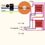
Like this?
I'm a little confused here. How much is the output voltage here? +/-27v or +/-54v?
Is it easy to modify the transformer so that both secondaries has a center tap?
Attachments
Hi,
your pic shows a toroid and your sizes seem more like a toroid.
The circuit shown in your pic will not work. Two rectifiers needs two secondary windings to give a dual polarity supply.
You can get a dual polarity supply from one rectifier with a centre tapped secondary, but your transformer appears to be single windings of different voltages and that is no good for power amplifier use.


For a split supply you need 2 seconadaries with the same voltage... which can be in the in the form of say 0V-26V-0V-26V, or a centretapped format 26V-0V-26V... or two similar single secondary transformers with seconadies in series to imitate the above..
I hope Nuuk wont get mad.
Nuuk hasn't got mad very often since he spent two weeks on Camiguin Island! 😀
- Status
- Not open for further replies.
- Home
- Amplifiers
- Chip Amps
- 13v + Lm3875 = ?