Hey All,
I hve a pair of Dnaco Mark VI monoblocks that I converted to a LTP 12Au7 front end and 6922AU7 driver section with KT88 outputs. After a few months of listening I'm not happy with the amps. They just sound a bit harsh at volume. (Ithink this may be caused by too much voltage on the 12au7"s. I recently built a pair of Mark III clones using a cascODE 6922 front end. Would the cascode be preferable?
Kevin
The LTP and cascode are such different circuits that it is a bit difficult to conceive that they might be alternatives for a given job. LTP is used when you need a balanced input and/or a balanced output, and are happy to lose a little gain and add a little noise but greatly reduce even-order distortion. Cascode is used when you need high gain and low input capacitance for low level signals so distortion is not a problem. Oh, and they have very different PSRR.
Sorry about the really poor typing. I was trying to to this while at work before the boss noticed what I was doing. I don't have balanced inputs or outputs and I don't need more gain. Getting a Mark VI apart is a bitch. And If I was going that far I thought I might use the cascode since I have four 6922's. But the original design used the LTP so I'll try to make that work.
But I still have these 6922's. Could you use a pair of cascode 6922's as a line amp?
Kevin
But I still have these 6922's. Could you use a pair of cascode 6922's as a line amp?
Kevin
I hve a pair of Dnaco Mark VI
I don't have balanced inputs or outputs
But the original design used the LTP so I'll try to make that work.
Kevin
If the first statement is true, both the 2nd and 3d are false.
Mark Vi is pentode VA > Concertina splitter > PPP finals.
Free Dynaco tube schematics
You may want to look here:
CURCIO AUDIO Dynaco Mark-4 Amplifier Upgrade
Curcio Audio Engineering (CAE) offer a 6922/6DJ8/6N1P Differential Cascode front end upgrade board for the MKIV. It has an integrated HV regulator on the board to address the fact that cascodes have low power supply rejection.
I've used these boards, they work well. Only problem I ever had was a "running water"/"surf" sort of sound from one card which turned out to be a microphonic tube and not a circuit fault at all.
Cheers,
Ian
Ian, that one sure doesn't look like a differential cascode to me. And no regulator:
http://www.dynaco-doctor.com/MK4-DVR-DOC.pdf
Do they make another board?
http://www.dynaco-doctor.com/MK4-DVR-DOC.pdf
Do they make another board?
... I was trying to to this while at work before the boss noticed what I was doing...Kevin
LOL. Been there done that.
😉
OOPS - is my face red.
I was thinking of this one - the MK3 "Premium Mod", their PCB-1A board or ASM-1A Kit.
http://www.dynaco-doctor.com/mk3des_3.htm
That is the one I have used. I used it with 6SN7 cathode followers after it to drive parallel push pull KT88.
It was only a prototype amp using Hammond 1650T Output Tranny and I only ever built the one channel but I liked it.
It sticks in my mind because I also tried that prototype monoblock with PAT4006 Plitron Torroidal Output Tranny and decided I liked the half the price Hammond better. It was also 5 or 6 years ago before I went off on the Baby Huey track.
The one I linked is cascode into a triode diffamp and seems to be the same circuit as MK3 "standard" upgrade board.
Sorry about that.
Cheers,
Ian
Last edited:
dgata,
That´s not the one.
The diff cascode was first presented in GA. I have also tried them but built them from GA instead of buying cards. I had them in a pair of MkIV mnay years ago. The late Bo Hansson of Opus3 also produced a amp, Candela, with the same front end and 6L6, that was no hit for me. Ian and have different opionions as I didn´t like this driver at all.
mr2racer,
No success until I combined the front-end with E182CC CF. Then it was OK but not more. AS pointed out by Ian this was for a pair of EL34. Driving two pairs of 6550/KT88 isn´t the same thing.
If you have built something with 12AU7 I can understand it sounds unsatisfactory.
Last edited:
Ian, that one sure doesn't look like a differential cascode to me. And no regulator:
http://www.dynaco-doctor.com/MK4-DVR-DOC.pdf
Do they make another board?
+1.
I think what the OP means is a LTP with the triode pair on the bottom having a triode pair fixed on the plates as in a cascode. IOW a balanced cascode, or a LTP cascode.
Attachments
Responses as I was busy trying to edit above.
Criticism of the CAE ASM-1A
I don't think they ran the 6DJ8 hard enough (too low a current).
What was right with the board
On board Maida Style HV Reg to address the fact that cascodes have next to no power supply rejection.
The cascode diffamp tail had a CCS which was driven off a common mode tap between the 2 outputs which helped enforce AC balance (but did'nt do anything for DC balance). Was never really convinced it had enough gain in the CCS arrangement. Also my experience since those experiments all those years ago is that you really need a cascode CCS in the diffamp tail get the best performance particularly at higher frequencies. Early effect and device capacitances limit performance otherwise. That (the device capacitance limiting impedance at higher frequancies) is also why I'm not a fan of LM317 and similar based CCS for amplifier front end circuits and why I would be a bit sus about a mosfet based CCS.
Better finish this off before the boss spots me too (+1 on above). I'm meant to be running response tests on a laser scanner.
Cheers,
Ian
revintage, that's the Curcio circuit from the '89 article in GA. I wasn't aware they sell boards with that topology. Do they? I might build one if I can get the boards.
Hey All,
DGTA, The 7199 is gone, as is the concertina. I replaced it with a LTP using 12AU7 as both preamp tube and phase splitter. The amp sounded like it was being over driven. So I checked some voltages. I have 500 volts across the KT88, (from plate to cathode). On the 12AU7 preamp I have 195 volts from plate to cathode, I think this is the problem as the limit for the 12AU7 is 180 volts. I have 181 volts across the phase splitter. Both 12au7's have 8 volts from grid to cathode. The preamp tube triodes are run in series. I think if I bring the voltages in line the amp should sound better.
Question, what would be the best voltage to shoot for? Just under 180? or maybe a bit lower? Do the 8 volts on the grids sound right? And should that be measured from grid to cathode? How likely is it that the preamp tubes were damaged by the over voltage?
If this doesn't fix it, I was thinking of converting to the 6922 cascode Joe Curcio designed for the Mark III. Would that have enough "drive" for a quad of KT88's. Or is there a better option?
Thanks everyone, Kevin
Last edited:
Been There; Done That
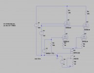
I did this project with a cascode LTP splitter/VA. It worked great, and avoided the need for a second gain stage. Cascoded the CCS for improved high frequency performance. The main DC rail is quiet enough that PSRR wasn't a problem here.
Cascoded LTPs are more common in solid state design, but there's no reason not to use 'em in hollow state designs as well.
Attachments

Kevin, if you post the schematic of your circuit, it would be relatively easy to comment.
Your description is confusing, not quite sure what you have there.
At any rate, the exact voltage across a tube is not critical and I promise you that the limit on the 12AU7 is NOT 180V. Look it up, one of the operating points listed on the data sheet is 250V.
Your description is confusing, not quite sure what you have there.
At any rate, the exact voltage across a tube is not critical and I promise you that the limit on the 12AU7 is NOT 180V. Look it up, one of the operating points listed on the data sheet is 250V.
Yeah you're right the max is 300 volts. Vhkf is 180 max, whatever that is. I only have a paper copy of the schematic. I'll try to get an electronic one and post it. So the voltages sound right then?
I did this project with a cascode LTP splitter/VA. It worked great, and avoided the need for a second gain stage.
I personally like that topology. But I have to say that "avoiding a second stage" is not a particularly useful feature to me. It uses 4 tube sections (not including the CF) and you can pretty much do any topology with 4 tube sections.
I'd be curious as to the "improved high frequency performance". Can you elaborate on the benefits? One of my test beds is the ubiquitous Williamson topology, no CCS anywhere and it has a high -3dB point somewhere north of 50kHz input to speaker, with no feedback or frequency shaping of any kind (except coupling caps). Would you consider that response inadequate, or do you define the performance in terms other than frequency response?
- Status
- Not open for further replies.
- Home
- Amplifiers
- Tubes / Valves
- 12U7 LTP vs. 6922 cascode