I'll try to get an electronic one and post it. So the voltages sound right then?
Do you have a scanner? 🙂
The voltage cannot "sound" right or wrong. Depends on the circuit. You have to understand how it works, what it was intended to do and how well it does that.
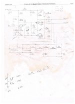
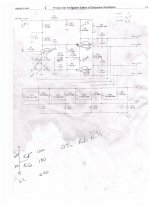
Sorry for the poor copy but its the best I could get from my poor original, simulacrum. I remember when I modified these that I had to go down on the cathode resistors to get them to flow any current. Bill Hardy, the man who gave me the original design said to parralell the preamp tube to get more current. I'll do the measurements and figure the current tonight. Is it possible there is too much current across the tubes?
II'd be curious as to the "improved high frequency performance". Can you elaborate on the benefits? One of my test beds is the ubiquitous Williamson topology, no CCS anywhere and it has a high -3dB point somewhere north of 50kHz input to speaker, with no feedback or frequency shaping of any kind (except coupling caps). Would you consider that response inadequate, or do you define the performance in terms other than frequency response?
I meant the high frequency performance of the CCS. Cascoding the BJTs helps break up the device capacitance to ground, which, at high frequencies, diverts AC to ground around the CCS, thereby spoiling the "CCS-ness".
The cascode, since it greatly reduces Cmiller, will always have better HF performance than a single triode -- that was the point: the high frequency performance of the grounded grid topology with the Hi-Z input of the grounded cathode. As for overall amp HF response, the greatest bottle neck is always the OPT. If you get fh ~= 50KHz from input to output, that's always pretty good.
"...Do you define the performance in terms other than frequency response?"
Yes: does the design have adequate phase margin for stability under gNFB.
MR2,
That's not what I would call an outstanding design 🙂 but that's for another discussion.
The circuit can work if calculated properly. I'm going to ignore the handwritten numbers and assume the input tube is a single, not 2 paralleled sections.
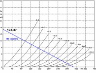
With 420V PSU and 195V at the plate (as you said in previous post), the input tube is drawing roughly (420-195)/(15k+18k) = 6.8mA. The B+ to the tube is 420-(6.8 x 15k) = 318V. With the resistors shown in the cathode, the tube is biased at (6.8 x 1.38) =-9.4V.
See the load line attached. The operating point we just determined doesn't quite exist on that plot, but it's in the ballpark with differences in tubes, etc. And it's not a bad operating point for that tube, although I would have chosen a larger plate load and lower bias. But it should work as is.
If any of the above assumptions are not what you have in there, just use the calcs I gave to figure out what you have.
There is no need to parallel the input tube for more current (why do you want more current?), you can draw all the current you want through one section. Personally I don't see much advantage to currents much higher than 7mA, in fact I run mine usually at less.
That's not what I would call an outstanding design 🙂 but that's for another discussion.
The circuit can work if calculated properly. I'm going to ignore the handwritten numbers and assume the input tube is a single, not 2 paralleled sections.
With 420V PSU and 195V at the plate (as you said in previous post), the input tube is drawing roughly (420-195)/(15k+18k) = 6.8mA. The B+ to the tube is 420-(6.8 x 15k) = 318V. With the resistors shown in the cathode, the tube is biased at (6.8 x 1.38) =-9.4V.
See the load line attached. The operating point we just determined doesn't quite exist on that plot, but it's in the ballpark with differences in tubes, etc. And it's not a bad operating point for that tube, although I would have chosen a larger plate load and lower bias. But it should work as is.
If any of the above assumptions are not what you have in there, just use the calcs I gave to figure out what you have.
There is no need to parallel the input tube for more current (why do you want more current?), you can draw all the current you want through one section. Personally I don't see much advantage to currents much higher than 7mA, in fact I run mine usually at less.
Attachments
Last edited:
Thanks for the help, dgta.
I confess these were the first tube amps I'd worked on. It was a steep learning curve. I've since built a pair of Dynaco Mark III's and an 8b. The Mark III's sounded better, and the 8b MUCH better. That's when I decided to go back to the VI's.
Some things you should know. My actual b+ is 535. I inserted a 5.6k 5watt resistor upstream of the schematic which gave me 413 volts. Aping your math at 6.6ma and 195 volts the load line gives an operating point closer to -8 volts, (which is what I measured from the grid to cathode).
As for the paralleled tube that wasn't my idea, it was the strategy of the man who gave me the circuit. I can cut the connections to the second triode very easily. Do you think that might help?
As for the circuit. Since I'm willing to build a new driver circuit. Is there one you might suggest? I would rather stay with a non-regulated circuit that is without PCBs or transistors. I just don't know enough about them yet. I have a pair of Tom Christiansens Maida PCb boards, so I'll get there.
And if I haven't run out of questions where did the 1.38 in your calculations come from?
Oh, and one other thing. I checked to make sure it wasn't frequency related. from 20 to 20k I didn't find any ringing or oscillation. So it seems the harshness might be the product of the circuit itself, or bad tubes?
8 volts, (which is what I measured from the grid to cathode).
Nothing wrong with 8V. But measure cathode to ground when possible, to avoid loading a high Z circuit. Unless you are sure the voltmeter has at least 10M impedance. It's the same voltage.
As for the paralleled tube that wasn't my idea, it was the strategy of the man who gave me the circuit. I can cut the connections to the second triode very easily. Do you think that might help?
There is no point in sharing 7mA between 2 tubes. Increasing the current in a single tube may bring it into a more linear region (or not), you have to look at the curves and work out several operating points and see which is better.
Paralleling tubes has benefits in some circumstances, which are beyond the scope of this discussion. But to do it just to "increase the current" doesn't make any sense. What for, just to draw more power from the PS?
Keep in mind that when you parallel 2 tubes, you are no longer on the same page. You now have an equivalent tube with different characteristics than the datasheet. Easy to deal with for a pro, but a beginner may not know which parts of a formula get doubled and which don't.
Since I'm willing to build a new driver circuit. Is there one you might suggest?
That's a question with a thousand answers, and each one starts with "depends". If you want to learn something, stick with this one and fix it, change it, play with it and gain understanding. If all you want is something that's guaranteed to work, copy a successful design EXACTLY in every minute detail and you're done.
And if I haven't run out of questions where did the 1.38 in your calculations come from?
Sum of your cathode resistors.
You didn't say if you are running negative feedback and how much. That makes a significant difference in the gain of the amp and likely the sound, depending. 2 stages of 12AU7, if run at certain operating points and without feedback, can indeed add to some serious non-linearity and poor sonics.
So it seems the harshness might be the product of the circuit itself, or bad tubes?
"Harshness" is subjective and can be anything. If the output looks real clean on the scope at all frequencies, I would look at the frequency response and distortion spectrum. 3rd order harmonics can sound "harsh". Hard to say from the limited data.
Think of it this way: Let's say I know just a tiny little bit about engines and I go build a 3sgte from a collection of parts I got here and there and some magazine articles. Then I say to you, it doesn't run right, it's got a weak spot in the midrange and I can't make 300WHP. You can try to help me on a forum, and it may be something simple or may take a while to work through all the possible issues.
Ok,
Pulled the amps apart and found some problems. First there was a 240,000k resistor between the + connection of the supply capacitor of the preamp tube connected to ground. It was in the original Dynaco but not in the new driver circuit. So I removed it. I rebiased the outputs to 70% of idle current. Also, the driver circuit supply/filter caps had the top bubbled up, like it was inflated. They were MA 100uf 100uf @500volts. I may have over voltaged them when I first built the amps, so I replaced them with JJ's, Also, for some reason on one of the output tubes most of the pins were corroded. I cleaned them up and the socket as well. I put a 5k pot across the 390pf feedback cap and listened to them today with "Golden Ears" MacGeorge. A large improvement but they still don't hold a candle to my 8b clone.
Could it be the JJ KT88's. Could I expect an improvement if I run them as triodes? (how do I do that by the way?) Or should I replace them with EL34's or 6550's? could this harshness be caused by high frequency parasitics? Also if the driver section is designed to run on 12AU7's are there other dual triodes I could try?
I know, its a lot of questions but any recommendations would be appreciated, Kevin
OK, again,
Took dgta's advice and excised the second 12AU7 preamp triode. HUGE difference. The bottom is much more robust. The harshness is gone!
One question, the .1uf coupling cap between the preamp and phase splitter (C3 if you can read the poor copy). I'd like to replace it with something really nice. In that position right now I have an orange drop. I was thinking of an Auricap or maybe a Solen. Any thoughts?
Kevin
Last edited:
As a general thought, I will offer this: you focus too much on changing parts for no good reason. You need to methodically go through it from one end of the other.
Verify that the deign is sound. If you can, simulate the circuit or ask someone to do it for you if you can't. Make sure that what you have in the amp is the same as you have on paper. Measure all dc and ac voltages, currents, gains and make sure they are within reason and within what you expect. Look at the waveforms at each stage (with a 1k sine wave, then 20Hz and 20kHz).
If you fully measure everything and it's not clear to you where a problem may be, post the schematic with all voltages and it will be easier for us to guide you.
ONLY when you have everything working properly, cleanly and producing the required output power should you consider listening to it and changing components to suit your taste.
AND, one more time. Make sure you test first without overall negative feedback. Only connect the NFB when it's fully debugged, otherwise you may get confused.
Last edited:
dgta,
I have been through the amps from one end to the other, many times. most of the new problems had to do with the lower amp being too close to a window that leaked air and allowed too much moisture into the lower amp.
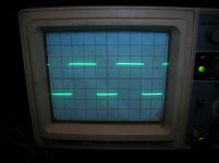
As for the design, I was given the driver section schematic by an experienced tech that has performed these modifications on the same amps. I measured all the voltages and they were right where they were expected to be. I swept the entire audio range from 20 to 20k with an ac signal. At very low frequencies the horizontals of the square wave were slightly angled. The positive slightly angled down, the negative up. But there was no ringing or overshoot and the square wave squared out by about 70hz. And I had a square wave right up until 20k. After about 18k my scope didn't have sufficient resolution to see perfect corners because I couldn't make the wave form large enough to really see it.
And maybe I overstated the harshness issue. I wouldn't say the amps sounded bad. They just weren't as good as I would like. Cleaning up the tube socket was obvious. Bill never gave me a "complete schematic" so the points where his driver section mated to the original Dynaco were a bit fuzzy. Hence the unnecessary 240k cap. I couldn't remember if the MA cap's tops were bubbled up or not when I got them. But as I had a set of JJ's, and since I wanted to move the ground for the cap to the star ground anyway that wasn't a big deal.
I bought these amps from an old friend who bought them in 1982. Both Rich and I have been listening to them for almost 30 years. And I can assure you they sound better now than they ever have.
I have used Solen coupling caps on all the amps I've built without any issues. The orange drops are known for being a 'bright cap.' And my displeasure with the amps is down to a fine enough point as to be the difference between two caps. I have a pair of Solen .12uf polypropylenes that I can replace the orange drops with tonight. It won't take but a few minutes and then I'll know. If the Solen isn't an improvement then I'll try Mallory 150 metalized polyester because they have a warmer midrange.
The Mark VI was intended to be used as a commercial amplifier. It was never intended to be an "audiophile" quality amp. But as Dynaco's transformers were always the best part of their amps I thought it might be worth trying to improve them.
Besides, your suggestion to ax the second triode on the preamp tube made a VERY big improvement.
I have been through the amps from one end to the other, many times. most of the new problems had to do with the lower amp being too close to a window that leaked air and allowed too much moisture into the lower amp.
As for the design, I was given the driver section schematic by an experienced tech that has performed these modifications on the same amps. I measured all the voltages and they were right where they were expected to be. I swept the entire audio range from 20 to 20k with an ac signal. At very low frequencies the horizontals of the square wave were slightly angled. The positive slightly angled down, the negative up. But there was no ringing or overshoot and the square wave squared out by about 70hz. And I had a square wave right up until 20k. After about 18k my scope didn't have sufficient resolution to see perfect corners because I couldn't make the wave form large enough to really see it.
And maybe I overstated the harshness issue. I wouldn't say the amps sounded bad. They just weren't as good as I would like. Cleaning up the tube socket was obvious. Bill never gave me a "complete schematic" so the points where his driver section mated to the original Dynaco were a bit fuzzy. Hence the unnecessary 240k cap. I couldn't remember if the MA cap's tops were bubbled up or not when I got them. But as I had a set of JJ's, and since I wanted to move the ground for the cap to the star ground anyway that wasn't a big deal.
I bought these amps from an old friend who bought them in 1982. Both Rich and I have been listening to them for almost 30 years. And I can assure you they sound better now than they ever have.
I have used Solen coupling caps on all the amps I've built without any issues. The orange drops are known for being a 'bright cap.' And my displeasure with the amps is down to a fine enough point as to be the difference between two caps. I have a pair of Solen .12uf polypropylenes that I can replace the orange drops with tonight. It won't take but a few minutes and then I'll know. If the Solen isn't an improvement then I'll try Mallory 150 metalized polyester because they have a warmer midrange.
The Mark VI was intended to be used as a commercial amplifier. It was never intended to be an "audiophile" quality amp. But as Dynaco's transformers were always the best part of their amps I thought it might be worth trying to improve them.
Besides, your suggestion to ax the second triode on the preamp tube made a VERY big improvement.
dgta,
If you mean in DB I'd have to figure out the math to give you that answer. I'm not great at math. What I can tell you is I'm really close now. The .12uf Solens were an improvement over the Orange Drops. I installed a 2.8k resistor for the feedback circuit. (The original was a 3k) And the amps lost a fuzz off the bottom and the center. And just a little 'life.' And when I say a fuzz I mean really small. But I have just a little too much feedback.
I need to order some resistors between 2.9 and 3.2k. And I'm going to order a pair of Auricaps as well. Its worth the twenty bucks to see if they really are better. When I get that done I get back to you.
Everything I've done in the past couple weeks has helped. I think the next iteration will be the last.
Kevin
If you can't calculate the global feedback, measure it. Measure the overall gain (input to speaker terminals) with and without feedback.
Once you have those 2 numbers, you can use an on-line calculator to get the dB number from the ratio.
Once you have those 2 numbers, you can use an on-line calculator to get the dB number from the ratio.
Last edited:
Hi,
I cut the feedback a little and got the center back. I would no longer characterize the sound as harsh, but still a little too bright.
With an input of .007 volts at 1k without feedback I got 4.04 volts output. With the feedback in place I have .93 volts output.
I don't know if you are familiar with this music but with Aimee Mann its too bright. With Tori Amos it seems much better. I'm going to try some acoustic jazz and then a little night music next.
My Friend Rob at Tube Depot thinks the Solen's might be a bit bright. Not as bright as the orange drops though. He recommended metalized polyester. Specifically Mallory 150 series. Any recommendations there?
Kevin
I'm the wrong guy to ask. Perhaps someone else can answer that.
My ears are not that golden🙂 If I take two identical amps and change coupling caps on one amp only (and all caps are good quality), I can not tell the difference. By that I mean I cannot pass a rigorous double-blind test. That is in spite of my extensive formal musical training.
If your ears can pass that test, by all means have at it 🙂.
Last edited:
- Status
- Not open for further replies.
- Home
- Amplifiers
- Tubes / Valves
- 12U7 LTP vs. 6922 cascode