Hey, Bryan!
This is the BIGGEST bread-board I have ever seen🙂 Do not kill yourself!
(Referring to the pic above.)
Regarding attenuation, you cannot go wrong with a DACT or the TKD 2P65S Stereo series stepped attenuator. The DACT can even be remote controlled by a kit from Bent Audio. I think that the standard 100K will work well.
Another alternative might be a ladder attenuator, but they usually cost a lot more if you are going for the best type of resistors in the ladder. And I am really not sure if a ladder attenuator is worth the extra money.
ALPS and Noble makes OK pots at a low price.
Very interesting to follow this thread by the way. A lot very good questions and answers.
Hey Guys,
Quick question.
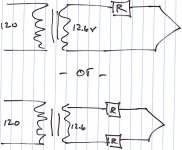
My heater voltage for the 12AX4's is high. I am using a resistor to bring it down to the appropriate range. Currently I am using 1 resistor, as in the top diagram. Is it fovorable to use two resistors, one on each leg, or does this not matter?
The transformers are center tapped, and grounded.
Thanks,
Bryan
Quick question.
My heater voltage for the 12AX4's is high. I am using a resistor to bring it down to the appropriate range. Currently I am using 1 resistor, as in the top diagram. Is it fovorable to use two resistors, one on each leg, or does this not matter?
The transformers are center tapped, and grounded.
Thanks,
Bryan
Attachments
Hi,
Since this is for a rectifier it won't matter, the two resistor scheme will spread the voltage/current a little better and will have the added advantage of not having all the heat in one single spot.
Cheers,😉
Is it fovorable to use two resistors, one on each leg, or does this not matter?
Since this is for a rectifier it won't matter, the two resistor scheme will spread the voltage/current a little better and will have the added advantage of not having all the heat in one single spot.
Cheers,😉
Hey Guys,
I was reading some posts at another site, and it raised a few questions.
I'm wondering what value bleeder resistors I should be using for the PS. I currenlty have 390K 2W. Is this good.
This is a choke input PS, drawing about 45mA total current. B+ is about 355 at the input choke, and 350 at the first filtering cap.
Thanks,
Bryan
Hi,
Yep....As this is a class A design it won't matter as long as the bleeder doesn't pull down the B+ you're fine.
The higher the value of the resistor, the longer it'll take for the PS to discharge.
For the electrolytic caps to remain formed this would be better, for you to work on it this could be dangerous.
Always check the B+ before sticking a hand in...
Cheers,😉
I currenlty have 390K 2W. Is this good.
Yep....As this is a class A design it won't matter as long as the bleeder doesn't pull down the B+ you're fine.
The higher the value of the resistor, the longer it'll take for the PS to discharge.
For the electrolytic caps to remain formed this would be better, for you to work on it this could be dangerous.
Always check the B+ before sticking a hand in...
Cheers,😉
Hi,
Not to worry there...not a single ounce of aluoxide in sight...😉
... and for the ASC PIO's?
Not to worry there...not a single ounce of aluoxide in sight...😉
Hi Guys,
I've allready ordered the top panel for the PS, which will hold the two chokes, and the 2 caps....
Now, as I ponder, there will be a long distance of wire between the VR regulator and CCS, which will be in the Pre-Amp chassis, and the last filter cap on the PS chassis. Would it be wise for me to add another LC or RC filter in the Pre-Amp chassis, to keep the final cap close to the audio circuitry?
Thanks,
Bryan
Hi,
Don't know how long long is but if we don't stop you right here and now you'll end up with more filters than there are in a pack of siggies...😀
With a good regulator you'll have riple in the millivolt range, add some fine MKPs in your preamp box, close to the anode resistors and it should be dead quiet.
Cheers,😉
Would it be wise for me to add another LC or RC filter in the Pre-Amp chassis, to keep the final cap close to the audio circuitry?
Don't know how long long is but if we don't stop you right here and now you'll end up with more filters than there are in a pack of siggies...😀
With a good regulator you'll have riple in the millivolt range, add some fine MKPs in your preamp box, close to the anode resistors and it should be dead quiet.
Cheers,😉
Bryan said:Hi Guys,
I've allready ordered the top panel for the PS, which will hold the two chokes, and the 2 caps....
Now, as I ponder, there will be a long distance of wire between the VR regulator and CCS, which will be in the Pre-Amp chassis, and the last filter cap on the PS chassis. Would it be wise for me to add another LC or RC filter in the Pre-Amp chassis, to keep the final cap close to the audio circuitry?
Thanks,
Bryan
You obviously are single or you have a very kind, patient, and supportive spouse. You must accept that perfection will never be achieved and merely strive to approach it within reason and budget. Step away from the soldering iron and breath in slowly............aaaannnnnndddd...exhale. Repeat as needed.
😉 😉 😉
Thanks G,
I assume you're talking about the breadboard.....
To clarify, the gf (girl-friend)/soon the be finacee, is THE MOST supportive, patient, and kind woman I have ever met, Not to mention *******ing HOT! I still dont know how I did it, but I try not to ask myslef that question....
Anyway, I've learned a little trick, to help keep the WAF in check.
Every couple weeks, we spend a few hours in the diamond district (47th and 6th in Manhattan), where I let her try on different settings and bands. The plan is for me to save some funds, and within a year or so pop the question.
Fortunately, she doesn't ask how much the DIY hobby costs, or else she would know the ring is more than a year away....😉
Any woman who can put up with me is a keeper! She has also developed a pretty good ear for audio, and can at times provide constructive criticism to my work.
Love, sweet Love!
Output transformers....
Hey Guys.....
I hope everyone had a good Memorial Day (for those of us who observe), and/or a nice weekend.
With respect to my linestage, I would like to have the option of using ballanced outputs.... Does anyone know the best way provide both single-ended AND ballanced outs that can be switched? I assume a good transformer could do the job?
Thoughts?
Thanks,
Bryan
A good transformer will do the job!
Alternatively, you could double up on the number of 12B4s and run them as CC-tail diff amps.
Alternatively, you could double up on the number of 12B4s and run them as CC-tail diff amps.
Thanks SY,
I things mostly set in place, and would like to use a transformer. Do you know of any particular units that excell above the rest?
I know Jensen makes some input transformers, but do they do output?
I will be using both single and ballanced, depending on the power amp I use.....
Thanks,
Bryan
I things mostly set in place, and would like to use a transformer. Do you know of any particular units that excell above the rest?
I know Jensen makes some input transformers, but do they do output?
I will be using both single and ballanced, depending on the power amp I use.....
Thanks,
Bryan
Hi Bryan,
I have learned so much reading your tube adventures, your questions and especially the kind support of our gurus like fdegrove, just to mention a few.
I am still impressed by your breadboard , wow; that"'s huge! 🙂
I am not suprised by the hum you had, since your signal wires are too long.
Anyway what is the outcome of your project and how does it sound?
In case you need some nice chassis try this site, they are quite good:
http://eshop.diyclub.biz/
Good luck with your projects and play it safe with high voltages!
Hey Kooltubes,
Thanks for the comments.
I have had a bunch of things happen during the final assembly of this beast, so it was put on the back bench for a while....
Currently, the PS is finished, and I am about to design the top plate for the audio circuitry. I've used the wood chassis from Welbourne, and anodized top plated from Front Pannel. The PS looks great, but is VERY heavy with all the chokes and trannies. I witt try to post a couple pics of the PS when I have some free time over the next few days.
I've also moved to the self-bias CCS for the 12B4A loading. I like it more than the battery version. I will comment more on that when I begin the final build of the audio circuitry. I've also included some timed mute circuits which will ground the outputs for 30 seconds on power up, and then connect to the rca's once everything is warm. Nice little touch. They instantly ground the outputs on power off.
Keep an eye out for some pics.
Bryan
Hi Bryan and others,
I have posted one thread few days ago asking questions about mr. Pimm's battery biased ccs. Sorry about that- I didn't saw that I could get my answers here (probably).
Bryan- could You tell me something more about the ccs since am kind of stucked in it.....
I have 12B4A preamp and want to turn over battery biased one. Also, intended current is 17mA to 20mA.
Simply I don't know how to bias it....
I have 4 pieces of 3.6V batteries (instead of 3.3V that mr. Pimm has used). I could manage to get another 4 pieces. So I could have 2*2 cells per channel for B1 and B2.
Would that change some values in the original design (sch attached)?
Also - what is the voltage drop across this ccs?
Many thanks and keep up the good work......
regards
daniel
Attachments
Here is what I have got as a reply from mr. Pimm himself (it was posted on the Tube Asylum). I thought it might fit here also so I will just copy/paste it....... 😀
**********************************
http://www.AudioAsylum.com/forums/tubediy/messages/67345.html
Posted by Gary P
Poster Info:
http://cgi.AudioAsylum.com/scripts/mail.pl?user_ID=2630&f=tubediy
Re: mr. pimm's baterry biased ccs q's
------------------------------
Hi,
Some answers...
-------my question------------
"First, mr. Gary uses 3.3V battery cells in the table in his article on
his
web page. I have 3.6V cells - and because of that I would need to
adjust
slightly the circuit. Would it be enough to use the same circuit as he
made
it and adjust it with the pot as in the sch or should I change some
values?"
---------his answer--------------
The difference between 3.3 volts and 3.6 volts is only 9%. Less
difference
than you will find in the turn-on voltage of different batches of
mosfets.
You might want to increase the value of R1 5% or so to hit the current
you
want.
---------my question----------
"Second, he has metioned that he uses 2,3 or 4 cells- I asume that he
use
them in series with eachother. So if I would decide to use 2 cells I
would
need 4 battery cells for the whole circuit, right?"
---------his answer---------
Yes, to do a 2 cell version would use 4 total per CCS. Performance is
better with the 4 cell version though.
----------my question---------
"Third, and most important of all, what is the voltage drop across that
ccs?"
---------his answer----------
The CCS doesn't really have a set voltage drop. It does have a minimum
voltage that has to be met or it won't work properly. The CCS also has
a
maximum voltage that if exceeded will cause the smoke in the parts to
escape, causing the CCS to not work properly once again .
Minimum voltage (hard clipping) is around 10 volts. Best to keep the
minimum voltage at during signal peak conditions to 20 volts or higher.
Good rule of thumb for maximum signal voltage is to have the same
voltage
across the CCS as the triode. In line stages where the signal is small
you
can run less voltage across the CCS.
The voltage across the CCS in a circuit is controled by the triode's
characterstics. The grid bias and plate current will determine what the
plate voltage will be at the chosen operating point. The remainder of
B+
will be on the CCS.
Hope this helps.
Gary
****************************
Gary thanks --- it helped a lot
😀 😀
Next Step
Hey Guys,
So, finally I am back on this project! I finished wiring up and testing the external power suply last night. So far so good. Of course, these were preliminary tests, as there are no loads etc attached to the PS. But, no shorts, no fuses blown, and no sparks! It looks really nice as well, but damn, it is heavy.
I will get out the photos ASAP.
So, I am still trying to determine what type of attenuator to use, and which input selector switch. I am looking at the goldpoints and the greyhills. Any thoughts as to ladder/shunt/etc?
Thanks,
Bryan
I think I am loosing my mind!
This project is pretty much finished, and now that I am listening, it seems that the bass is a little off....
Attached is the current schematic as it is now built.
Both chassis are done, and looking good. The sound seems a little flat in the lower end. The only changes I've made from the breadboard are removing the cathode bypass, adding in a DACT 50K attenuated pot, and I've changed the output coupling cap to a 2mF Mundorf Silver. I seem to be loosing bass response somehere. Am I missing something obvious, or could this simply be a matter of waiting for new parts to "burn in?"
I am driving my ARC VT100 MK II with an input impedance of 100K.
Any thoughts?
Attachments

- Status
- Not open for further replies.
- Home
- Amplifiers
- Tubes / Valves
- 12B4A Linestage