Hmmm,
I just looked at the pinouts for the 12B4A, and I now have two more quick questions....
I was thinking that my noise may be some oscillation, and thought about maybe trying some grid stoppers.
I currently have the input connected to pin 2. Pin 7 is empty.
Should I tie pin 2 and 7 together?
Also, if I choose to try the grid stoppers, would I ise 2 resistors, on to pin 2 and the other to pin 7, and thn join the two ends of these resistors together and attach the input to this junction?
Also, what is the purpose of the heater center tap???
Thanks for the help,
Bryan
Hi,
If you don't plan on using a gridstopper then, yes
Yes.
It allows to heat the tube with either 12.6 or 6.3 V.
Cheers,😉
Should I tie pin 2 and 7 together?
If you don't plan on using a gridstopper then, yes
and thn join the two ends of these resistors together and attach the input to this junction?
Yes.
Also, what is the purpose of the heater center tap???
It allows to heat the tube with either 12.6 or 6.3 V.
Cheers,😉
Thanks Frank!
Could you please explain the correct hookup of the heater at both voltages?
Thanks,
Bryan
Could you please explain the correct hookup of the heater at both voltages?
Thanks,
Bryan
Hi,
Series connection:
12.6 V 300mA, connect heater supply to pins 4 & 5.
Parallel connection:
6.3 V 600mA, connect either pins 3 & 5 or pins 3 & 5 together and hook up heater supply to pins 4 & 5.
Cheers, 😉
Could you please explain the correct hookup of the heater at both voltages?
Series connection:
12.6 V 300mA, connect heater supply to pins 4 & 5.
Parallel connection:
6.3 V 600mA, connect either pins 3 & 5 or pins 3 & 5 together and hook up heater supply to pins 4 & 5.
Cheers, 😉
Attachments
fdegrove said:connect either pins 3 & 5 or pins 3 & 5 together
Need another cup of coffee Frank?
dave
Hi,
Ooops...
3 & 4 or 3 & 5.
Thank god I'm not working in a nuclear plant...
Cheers,😉
Need another cup of coffee Frank?
Ooops...
3 & 4 or 3 & 5.
Thank god I'm not working in a nuclear plant...
Cheers,😉
Hey all,
So things are progressing, though not at the pace I'd like, due to graduate school "responsibilities"😡
Nevertheless, I've found some time to tinker today, and in tweaking some of the grounds, I've gotten the noise even lower.
So, this leads up to my next couple questions....
1. When I raise my volume, the hum is increased. I currently am using cheap 22 gauge solid copper for the inputs, with the signal and ground twisted. They run quite long lengths currently. I would imagine that these wires are acting like antennas, hence some hum/noise. But, if I only hear an increase in the hum with the volume pot turned, would this mean that the humm is coming from the input wiring, and not the PS of the amp? That is, if the PS were the cause of the hum, would it's intensity be altered by modulating the volume pot?
2. I'm thinking about trying some other topologies, like choke loading, and maybe trying an output transformer. Could you guys give me your suggestions as to good quality plate chokes and output trannies I may want to try?
Thanks for the continued help,
Bryan
Hi,
Not when their terminated they're not.
That indicates the circuit amplifies the hum as the volume is increased.
Seems there's a groundloop somewhere, maybe the volpot itself?
That won't solve the problem, would it?
Cheers,😉
I would imagine that these wires are acting like antennas, hence some hum/noise.
Not when their terminated they're not.
When I raise my volume, the hum is increased.
That indicates the circuit amplifies the hum as the volume is increased.
Seems there's a groundloop somewhere, maybe the volpot itself?
I'm thinking about trying some other topologies, like choke loading, and maybe trying an output transformer
That won't solve the problem, would it?
Cheers,😉
Hey Frank,
Let me aks about the pot. It is a 2 channel 100K pot. It has three lugs per channel, plus an additional lug on the underside of the pot. What is the proper way to hook this up? I think i have the upper three lugs correctly wiredc, but teh bottom lug is not attached.
I know the alternate topologies wouldn't help the hum, that was not the idea behind trying other topologies. I want to hear what else this thing can do, and deside in the final form.
I will fix all the kinks before trying something new, but I figured I'd do some research in the interim.
Any suggestions?
Thanks,
Bryan
Hi,
The top three lugs should be standard setup.
The bottom one I haven't seen on a volctrl yet but it could be a lug to earth the metal housing.
You can check it with a meter if you like. Otherwise just give it a try and add it to your star earthing.
Is your chassis earthed? Does hum increase when you touch it?
There are a number of these troubleshooting tips but more often than not it's just an oversight.
You know, a loose earthing wire, a ground connection made twice,...stuff like that.
I see no particular reason for the circuit itself to be particularly prone to hum so there's hope. 😉
Cheers,😉
What is the proper way to hook this up?
The top three lugs should be standard setup.
The bottom one I haven't seen on a volctrl yet but it could be a lug to earth the metal housing.
You can check it with a meter if you like. Otherwise just give it a try and add it to your star earthing.
Is your chassis earthed? Does hum increase when you touch it?
There are a number of these troubleshooting tips but more often than not it's just an oversight.
You know, a loose earthing wire, a ground connection made twice,...stuff like that.
I see no particular reason for the circuit itself to be particularly prone to hum so there's hope. 😉
Cheers,😉
extra lug
Hi,
My guess is that the extra lug is a tap for a loudness compensation circuit, should you wish to use such a thing. Is it a RS Alps by any chance?
Michael
Hi,
My guess is that the extra lug is a tap for a loudness compensation circuit, should you wish to use such a thing. Is it a RS Alps by any chance?
Michael
Hi,
Gosh...yes...Had completely forgotten about that Fletcher-Munson thingie.
I have a feeling you're spot on here...
Cheers,😉
My guess is that the extra lug is a tap for a loudness compensation circuit,
Gosh...yes...Had completely forgotten about that Fletcher-Munson thingie.
I have a feeling you're spot on here...
Cheers,😉
Frank,
When I ground the fourth lug, I loose signal, so this seems to ground this signal directly???
No chassis, so I couldn't answer the question about touching it...
Let me run through how I have the input and output wired.
The input signal goes to the first lug on the volctrl. The grond wire from the input goes directly to the lowest "earth" point on the amp (tag strip which contain all the PS earth points). The second lug of the volctrl goes to the grid stopper resistor. The third point on the volctrl goes to the star below the 12B4A (a tag strip which contains all the grounds related to the 12B4A, which is connected to the "earth" tag strip with one wire). The output ground is attached to the 12B4A star tag strip.
Is this correct?
Also, the PS is grounded with two wires. I have the second cap grounded along with the VR tubes. These grounds go to the "earth" tag strip mentioned above. This strip is then wired to the mains earth terminal.
Do you see any potential problems with this configuration?
Thanks,
Bryan
Hi,
O.K. This is the one on the left hand side with you in front of the shaft.
That's not how it's supposed to be done. The input ground wire should be soldered to the lug on the right hand side, than taken from there to the ground of your first triode which is than daisy chained to the star earth.
Yes, that's the output which ground should first go to the pots' groundlug. The earthing is than done by the wire as described previously. No need for a double run here.
From the rest I gather you have grouped some local earth points together which you finally ground at a common point. One for the signal carrying circuit, the other for the PS.
Not true star earthing but it should be hum free nonetheless.
If it isn't clear, let me know. I'll try to draw something up tomorrow.
Cheers,😉
The input signal goes to the first lug on the volctrl.
O.K. This is the one on the left hand side with you in front of the shaft.
The grond wire from the input goes directly to the lowest "earth" point on the amp (tag strip which contain all the PS earth points).
That's not how it's supposed to be done. The input ground wire should be soldered to the lug on the right hand side, than taken from there to the ground of your first triode which is than daisy chained to the star earth.
The second lug of the volctrl goes to the grid stopper resistor.
Yes, that's the output which ground should first go to the pots' groundlug. The earthing is than done by the wire as described previously. No need for a double run here.
From the rest I gather you have grouped some local earth points together which you finally ground at a common point. One for the signal carrying circuit, the other for the PS.
Not true star earthing but it should be hum free nonetheless.
If it isn't clear, let me know. I'll try to draw something up tomorrow.
Cheers,😉
Frank,
I re-wired it, and it is still giving me some hum. I'm going to play with the choke orientation and see if that helps.....
On another note, what are the signs of a mosfet in a CCS that was overheated? That is, when I first tested the CCS, and there was no sink on the piece, it did encounter "excessive" temperature for a slight moment. Would it be possible that this would cause the device to cause noise in the circuit, similar to the staitic-type noise that I am hearing?
Thanks,
Bryan
Hi,
Yes, that could cause that dreaded noise indeed.
Happens sometimes even when you overheat them with a soldering iron.
Cheers,😉
Would it be possible that this would cause the device to cause noise in the circuit, similar to the staitic-type noise that I am hearing?
Yes, that could cause that dreaded noise indeed.
Happens sometimes even when you overheat them with a soldering iron.
Cheers,😉
Inspired by this thread I am thinking about building a 12B4A linestage, too.
I am especially interested in a transformer coupled version, either parafeed or standard single ended. I have two questions regarding this topology:
1) Is it OK to short the output for muting with both topologies (SE/Parafeed)?
2) When adding an extra output for a sub, will it be OK to just use a split or should I use some kind of transformer on the leg going to the sub (to isolate it from the main output)?
BTW: Have a look at http://www.jacmusic.com. There is a DIY expo/trade show in the south of Germany in June. 🙂
Hi,
Should be O.K.
I think that kinda depends on what secondary impedance is but it could be done IMO.
Either two secondaries or an xtra xformer may be closer to the ideal but I'm no expert on that.
Cheers,😉
1) Is it OK to short the output for muting with both topologies (SE/Parafeed)?
Should be O.K.
2) When adding an extra output for a sub, will it be OK to just use a split or should I use some kind of transformer on the leg going to the sub (to isolate it from the main output)?
I think that kinda depends on what secondary impedance is but it could be done IMO.
Either two secondaries or an xtra xformer may be closer to the ideal but I'm no expert on that.
Cheers,😉
Thank you Frank 🙂
I just found out that S&B has a transformer that might be suitable for the extra sub-output, the LO410 Line Driver transformer.
I just found out that S&B has a transformer that might be suitable for the extra sub-output, the LO410 Line Driver transformer.
Hey Guys,
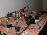
I'm about to plan the process of turing this bread-boarded beast into a refined, packaged beauty. This being said, I will need to purchase some "quality" components for the final version.
Attenuation. Stepped attenuator. Dact? Any suggestions as to the value which would be best in my application, and then the type of attenuator? Ladder, shunt???
Thanks,
Bryan
Attachments
- Status
- Not open for further replies.
- Home
- Amplifiers
- Tubes / Valves
- 12B4A Linestage