Hello,
I am a newbie into tubesc and for this reason i decided to buy two PCB`s from Ebay of a preamplifier with tone controls (already assembled) and final stage EL84SE.
The final stage alone works almost good i`d say (not the biggest problem right now), but when i connect the preamp it starts to hum loudly.
http://sendvid.com/x1fmyqr2
The preamp does a good tone correction and when i turn the volume up, the hum is covered by the music.
More data:
I have soviet tubes in the final stage: 6P14P + 6N1P. Some measurements:
6P14P:
Vp - 232v
Rk - 150 ohm
Rs - 2,2K
Vk - 6,01v, respectively 5,69v
Vs - 20,7v
Ik = Vk/Rk = 40mA, respectively 38mA
6N1P:
Vp - 72,2v, respectively 67v (?! is it correct that low?)
Rk = 1K - 1,19v, respectively 1,13v
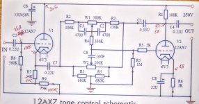
I have ECC82 in preamp although it was configured for ECC83/12AX7 (I don't have at hand ECC83 and i don't need much gain since i intend to play music from the computer only). Measurements:
How can this problem be corrected? I see low plate voltages at V2. They placed the corrector between two distinct tubes, not between triodes in the same envelope...
I am a newbie into tubesc and for this reason i decided to buy two PCB`s from Ebay of a preamplifier with tone controls (already assembled) and final stage EL84SE.
An externally hosted image should be here but it was not working when we last tested it.
An externally hosted image should be here but it was not working when we last tested it.
An externally hosted image should be here but it was not working when we last tested it.
An externally hosted image should be here but it was not working when we last tested it.
An externally hosted image should be here but it was not working when we last tested it.
The final stage alone works almost good i`d say (not the biggest problem right now), but when i connect the preamp it starts to hum loudly.
http://sendvid.com/x1fmyqr2
The preamp does a good tone correction and when i turn the volume up, the hum is covered by the music.
More data:
I have soviet tubes in the final stage: 6P14P + 6N1P. Some measurements:
An externally hosted image should be here but it was not working when we last tested it.
6P14P:
Vp - 232v
Rk - 150 ohm
Rs - 2,2K
Vk - 6,01v, respectively 5,69v
Vs - 20,7v
Ik = Vk/Rk = 40mA, respectively 38mA
6N1P:
Vp - 72,2v, respectively 67v (?! is it correct that low?)
Rk = 1K - 1,19v, respectively 1,13v
I have ECC82 in preamp although it was configured for ECC83/12AX7 (I don't have at hand ECC83 and i don't need much gain since i intend to play music from the computer only). Measurements:
An externally hosted image should be here but it was not working when we last tested it.
How can this problem be corrected? I see low plate voltages at V2. They placed the corrector between two distinct tubes, not between triodes in the same envelope...
Last edited:
First, welcome to diyaudio, Your schematic is too small. Can't read.
Assuming Vs = screen voltage of the output tube. 20.7V is too low. Was there a typo like it is 200.7V? If it is 20.7V I would start finding out why it is that low first.
Assuming Vs = screen voltage of the output tube. 20.7V is too low. Was there a typo like it is 200.7V? If it is 20.7V I would start finding out why it is that low first.
First of all, your idea of simply subsituting 12au7 for 12ax7 is problematic. For one, the tube is now not biased properly, and for another, the tone controls are now compromised, as the plate resistance of the 2 tubes are very different.
In any case, you need to provide details on how you actually constructed the project for 1) grounding, and 2) heater in order to figure out what is going on.
In any case, you need to provide details on how you actually constructed the project for 1) grounding, and 2) heater in order to figure out what is going on.
Sorry, now i see that the images don`t enlarge after click. So here are the links (the pictures enlarge even more after click)
Preamp:
Tone control Baxandal connection diagram 12AX7 v1 — Postimage.org
Preamp schematic with measurements:
IMG_20180104_183624~2 — Postimage.org
Final stage PCB:
100_4167 — Postimage.org
100_4169 — Postimage.org
Final stage schematic and voltages:
IMG_20180103_194704~2 — Postimage.org
Yes, the idea of replacing 12ax7 with 12au7 is problematic, but as far as i read, there would be needed only minor changes of the resistors. I assume that is the major part of the problem.
Voltage across Rs (2K2) is indeed 20,7v. Both channels share the same screen resistor 2K2 (top of PCB).
An externally hosted image should be here but it was not working when we last tested it.
An externally hosted image should be here but it was not working when we last tested it.
An externally hosted image should be here but it was not working when we last tested it.
An externally hosted image should be here but it was not working when we last tested it.
An externally hosted image should be here but it was not working when we last tested it.
On the preamp, 56V on the Cathode resistor 1K = 56/1000 = 56mA. Also There is less than 1V between the Plate and Cathode. I think something is connected wrong in your pre-amp beside the 12AU7 tube.
As far as i checked visually, there is nothing wrong connected (it came already assembled). I will check the parts to see if they have the specified values. It would be odd though to have two bad resistors or caps (56v are for both halves of tube).
Comparing more schematics of preamps built around 12AX7, i notice the bias resistor of the first tube is of larger value: 25K, where other designs use much less: 1K5 to 2K5...
Practical Tone Controls.
Comparing more schematics of preamps built around 12AX7, i notice the bias resistor of the first tube is of larger value: 25K, where other designs use much less: 1K5 to 2K5...
Practical Tone Controls.
Hi,
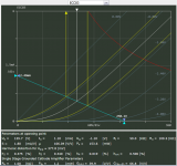
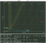
It can be seen from the load lines for 12ax7 and 12au7 that the preamp should work. The input stage is a cathode follower and the change of the output impedance is very small to affect the function of the tone stack. Only measurment that looks wrong is the 55,6-56V at the output cathode. Do you find any DC at the grid of this triode (R5)?
20,7V/2,2k= 9,4mA. That's 4,7mA per screen. It's OK.
Attachments
Thank you for your time.
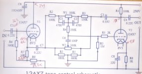
I checked the voltage on the grids of preamp triodes.
On the output triode - zero volts on grids (pins 2 and 7 against GND).
Input triode: 15,24, respectively 15,23 v...
Picture: I added the grid voltage of the triodes.
IMG_20180105_225116~2 — Postimage.org
 [/url]
I checked the voltage on the grids of preamp triodes.
On the output triode - zero volts on grids (pins 2 and 7 against GND).
Input triode: 15,24, respectively 15,23 v...
Picture: I added the grid voltage of the triodes.
IMG_20180105_225116~2 — Postimage.org
Which pre-amp tube do you want to use 6N1p or ECC82? These are completely different tubes. On the first stage, R7 resistor is wrong I think. It should be more like 2.5K for ECC82 and 250 Ohms for 6N1p
On the final stage board i have 6N1P and on the tone control board i have ECC82 (6N1P has diffrent wiring for the heater).. I will change R7 to see what happens.
The tone controls are working, the problem is that the hum from the preamp is so loud it covers the useful signal...
The tone controls are working, the problem is that the hum from the preamp is so loud it covers the useful signal...
@V2: 0V from grind to ground is correct. 57-56V from anode to ground is correct. 56-55,6V from cathode to ground is wrong. It should be around 1,9V.
@V1: There should be left around 190V from cathode to ground. I assume that the designer of the circuit aimed for self bias but in this case there are two mistakes. The output to the tone stack should be taken from the junction of R7, R9 and R7 should be 1k and R9 should be 100k.
@V1: There should be left around 190V from cathode to ground. I assume that the designer of the circuit aimed for self bias but in this case there are two mistakes. The output to the tone stack should be taken from the junction of R7, R9 and R7 should be 1k and R9 should be 100k.
I don't think so. Can you explain why?The output to the tone stack should be taken from the junction of R7, R9.
After you change R7, measure plate voltage and cathode voltages of both tubes V1, V2 and inform here.
Last edited:
I have changed R7 to 1K and R9 to 100K.
Voltages V1:
Vp - 247v
Vk - 188v (both)
Vg - 26,8v
Voltages V2:
Vp - 57v, respectively 56v
Vk - 1,8v (both)
The hum is still present. I notice the bass is not so strong anymore.
I also notice that when i connect the voltmeter from V1 cathodes to GND, the hum dissappers for half a second.
IMG_20180106_201221~2 — Postimage.org
Attachments
I have changed R7 to 1K and R9 to 100K.
Voltages V1:
Vp - 247v
Vk - 188v (both)
Vg - 26,8v
Voltages V2:
Vp - 57v, respectively 56v
Vk - 1,8v (both)
The hum is still present. I notice the bass is not so strong anymore.
I also notice that when i connect the voltmeter from V1 cathodes to GND, the hum dissappers for half a second.
IMG_20180106_201221~2 — Postimage.org
V2: OK
V1: Correct Vp and Vk. Wrong Vg.
I don't think so. Can you explain why?
...
Vg=26,8V. It should be Vk (188V)-1,8V. The triode won't bias.
Edit: What is the nominal voltage of C5?
Last edited:
I`m sorry. I thought you disagrred only about where the tone stack should be connected.
You both agreed that R7 is incorrect...
You both agreed that R7 is incorrect...
Correction... Yes, the output from V1 can be taken from both sides of R7. Taken between R7 and R9 helps to prevent oscillations. Perhaps this is what explains the voltmeter effect?
- Status
- Not open for further replies.
- Home
- Amplifiers
- Tubes / Valves
- 12AX7 tone corrector + EL84 SE