Everything seems OK except the grid of the first triode. For the given Vg, Vp and Vk should measure different also. I assume it's not the tubes since both channels measure the same. Check the pcb for any flaws. What type of voltmeter do you use? Some of them do not measure accurately at high impedance.
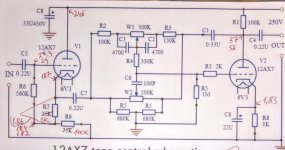
If you are willing to stay with ECC82 , then I would suggest to change R1-R9 to 22k and R7-R8 to 680 ohm for higher headroom and driving ability. See pic. In this case though, you may have to tweak C1. I can't help you much on this.
If you are willing to stay with ECC82 , then I would suggest to change R1-R9 to 22k and R7-R8 to 680 ohm for higher headroom and driving ability. See pic. In this case though, you may have to tweak C1. I can't help you much on this.
Attachments
I powered the preamp from a diffrent B+ supply than the final stage and it still has the hum. The circuit looks simple, the PCB is OK. I would have expected such a loud hum if i made the circuit with long wires...
I used diffrent tubes. Same result. I bought two ECC83, hum still present...
The voltmeter is a cheap chinese one. I don t thinl that's the problem.. It should give bad reading everywhere...
I used diffrent tubes. Same result. I bought two ECC83, hum still present...
The voltmeter is a cheap chinese one. I don t thinl that's the problem.. It should give bad reading everywhere...
Last edited:
The incorrect voltage on grid of V1 can be the source of the hum? Immediately after turning off the supply, the sound is very clean and stays so 2 or 3 seconds until the B+ capacitors discharge.
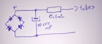
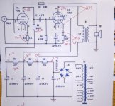
What is the heaters supply? AC or DC should be referred at least to ground. Better DC elevated so that Vkh do not exceed the max 100V for this tube.
THe heaters supply is DC filtered with 10.000uF. Not referenced to groud. It is floating.
All tube heaters are powered in paralell.
All tube heaters are powered in paralell.
Attachments
Last edited:
Thank you all. Solved. It was from the ungrounded heaters supply. Now i think everything is OK...
I have made some adjustments to reduse the hiss and hum. The sound is very clear and tone adjustments are good.
1. I have adjusted the negative feed-back in the final stage using an 100k pot to see what value is best for lower noise. I determined that the lowest noise is around the value of 3K3, but the output power was also reduced. I decided to solder a 10k resistor as NFB for both channels. At 10K, the noise is acceptable, almost i cannot hear it at 20 cm from the speakers. THe ticking of the clock on the desk seems loud 🙂 .
Is it OK with such a value?
These are the other values i have measured with hot tubes:
6P14P:
Vp (pin 3-7): 232v, 235v;
Vp (pin 7 - GND): 240v;
Rs: 2K2
Vs: 22v;
Rk: 150 ohms;
Vk: 6,02v, 5,6v.
Ik= Vk/Rk= 40mA
According to site http://www.tedweber....s1/calcbias.htm those values account for 38mA plate current and plate dissipation of 9W.
I think there is room for more power. According to datasheet, the maximum plate voltage is 48mA.
2. In the final stage i changed the soviet 6N1P with E88CC (Zaerix) for reasons of filament current: 600mA 6N1P vs 300mA E88CC. I don't see any diffrences in the quality of sound.
But i have very low anode voltage:41v and 30v ?!
Cathode: 1,23v, 1,33v (Rk: 1K)
Attachments
I guess Vs is the voltage drop accross the screen resistor. From this we can find the current for each screen which in your amp seems correct. The screen voltage is between screen and cathode.
The max power for 6p14p is 14W. Usually we stay bellow 80% and this is 11W. For plate voltage 235V you can bias up to 48mA.
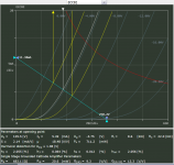
The load resistor 100k was already heavy for 6n1p. For ecc88 better decrease to 50k or at least increase the cathode resistor to 2,2k. Even better Ra=33k and Rk=560 ohm. Try to learn how to draw load lines. Perhaps this could help you to start with Triode / Pentode Loadline Simulator v.1.0 (20161216 [url]www.trioda.com)[/URL]
The max power for 6p14p is 14W. Usually we stay bellow 80% and this is 11W. For plate voltage 235V you can bias up to 48mA.
The load resistor 100k was already heavy for 6n1p. For ecc88 better decrease to 50k or at least increase the cathode resistor to 2,2k. Even better Ra=33k and Rk=560 ohm. Try to learn how to draw load lines. Perhaps this could help you to start with Triode / Pentode Loadline Simulator v.1.0 (20161216 [url]www.trioda.com)[/URL]
I have checked now the link and i get the famous error 404 and something written in polish. Maybe tomorrow they will repair the link. I read about load lines, but that calculator would be more useful. I have continued the adjustments empirically:
1. Because i had different voltages on the anodes of the ECC88 i changed the tube with a NOS ECC88. This time i measure the same voltage: 73v on both plates. Is this not still low? In the datasheet i see the standard is 250v.
I have Ra-22k (i didn't find a 33k) and Rk-560 ohm.
2. For final stage:
- I removed the 2K2 screen resistor, as i have seen it is omitted in other schematics.
- I changed the cathode resistor to 100 ohm
- According to Weber Bias Calculator i have 46mA plate current.
3. I tried to make a switch for triode/pentode mode. I was not impressed with the results of triode mode. I can say it's almost only half power. I thought the sound would be different. I will experiment more...
Attachments

Ra=22k and Rk=560 ohm is fine for ecc88. You could increase B+ (and plate voltage) by lowering the value of the last resistor in the psu (15k?). It drops too much voltage now that the current has been increased in the first stage.
I wouldn't suggest to remove the screen resistor. Keep at least 1k there for safety reasons.
I wouldn't suggest to remove the screen resistor. Keep at least 1k there for safety reasons.
Today i haven`t done much. I mostly listened to it. It has a nice sound, very warm. I soldered a 1K screen resistor (both tubes share the same screen resistor). I lowered the 15k resistor to 1K, now the plates of ECC88 have 110v.
Further questions:
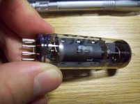
1. I have this EL84 tube (Tungsram) which i took from a radio that was thrown at the garbage. It has shiny parts on both sides. Does this mean it was heavily used? In my amplifier i don't see any sound diffrences.
2. Can i use tantalum capacitors as cathode capacitors for final stage and preamplifier? For example 100uF/25v it's enough considering that the voltage across Rk i measure 6v. I'm considering tantalum because they last forever as far as i know. Their value does not modify over time.
3. If i use a 3K resistor for negative feed-back, is it a problem? At that value i have the lowest noise possible. On the original schematik it was mentioned 36k, on others i have seen from 35k to 100k...
Further questions:
1. I have this EL84 tube (Tungsram) which i took from a radio that was thrown at the garbage. It has shiny parts on both sides. Does this mean it was heavily used? In my amplifier i don't see any sound diffrences.
2. Can i use tantalum capacitors as cathode capacitors for final stage and preamplifier? For example 100uF/25v it's enough considering that the voltage across Rk i measure 6v. I'm considering tantalum because they last forever as far as i know. Their value does not modify over time.
3. If i use a 3K resistor for negative feed-back, is it a problem? At that value i have the lowest noise possible. On the original schematik it was mentioned 36k, on others i have seen from 35k to 100k...
Attachments
Last edited:
It is somewhere here that my limited knowledge proves insufficient. Actualy, all the answers that I gave so far can be found to websites like this for example How to design valve guitar amplifiers . His book is also very good.
Generally, tantalium caps should be avoided in tube amps because they are not stable with temperature. NFB needs bench equipment to adjust properly. That said, 3k allow too much feedback. Better fight noise in its origin.
Generally, tantalium caps should be avoided in tube amps because they are not stable with temperature. NFB needs bench equipment to adjust properly. That said, 3k allow too much feedback. Better fight noise in its origin.
After listening a few days to the amplifier i noticed that the screen resistor (2K2) is getting hot and the sound is crackling if i take out the NFB. Like in this video:
VID 20180115 204746 - Sendvid
I also noticed a small decrease of output power.
I tried to measure the plate voltage of the tubes and i can't get any reading. The sound decreases when i touch pin 7 of EL84 with the test lead.
I added a volume pot between preamp and final stage, 1M log. The 1M grid leak resistors are still in place. I'm not impressed with the volume i can set by turning the pot: after 1/3 of the rotation the sound is at maximum...
Attachments

Last edited:
I don't know if I can answer to this for sure, just a few ideas. I think you should remove the grid leak resistor and try with the pot alone. You need the highest input impedance in your amp since your line stage has a very high output impedance. You can't do much about this but there is something else you should change in the amp input. You have bias it at -1,23/-1,35V. This is too small headroom given the tubes don't like to go below -1V and closer to zero. That may explain the behaviour of the pot and the crackling sound (clipping?). Does this sound occurs at idle or at full power?
And a query: Where do you put the voltmeters' leads to measure that 27,3V at the line stage input?
And a query: Where do you put the voltmeters' leads to measure that 27,3V at the line stage input?
Some more testing today. I took out the volume pot and kept the screen grid leak resistors and the problem was almost solved. Now i have the values in the picture.
For the final stage
1. To ECC82 i changed Rk back to 1K and kept R2-22K. Now the bias voltage is -2,43v. R6 changed to 10K.
2. To EL84 I left the parts as i changed them before: Rk - 100ohm. Rs (2K2) gets quite hot (it didn't get black after 3 hours of listening). I can change it with 5W one if getting hot it's not a big problem. With these values i have 10W plate dissipation and 42mA current.
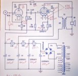
Looking at the picture, how do these values seem ? I think that here are a lot of people that such a simple amp is like a game and understand in an instant what it is about 🙂
Preamp stage
I measured the line stage input (27,3v) connecting the voltmeter leads between grid and GND. At the intersection of R6, R7 and R9 i have 184v.
For the final stage
1. To ECC82 i changed Rk back to 1K and kept R2-22K. Now the bias voltage is -2,43v. R6 changed to 10K.
2. To EL84 I left the parts as i changed them before: Rk - 100ohm. Rs (2K2) gets quite hot (it didn't get black after 3 hours of listening). I can change it with 5W one if getting hot it's not a big problem. With these values i have 10W plate dissipation and 42mA current.
Looking at the picture, how do these values seem ? I think that here are a lot of people that such a simple amp is like a game and understand in an instant what it is about 🙂
Preamp stage
I measured the line stage input (27,3v) connecting the voltmeter leads between grid and GND. At the intersection of R6, R7 and R9 i have 184v.
Attachments

At the amp input I believe you have ECC88(?) not ECC82. Electricaly seems OK. I hope it sounds good for your taste. If you practice with load lines you will be able to play a lot with operating points. Changing the parameters of this stage you also change the current demant. This will affect the resistors at the psu. The screen resistor is part of this. Increasing the current to ECC88 increased the voltage drop at the screen resistor. That's why you had to oversize it. Again, using simple Ohm's law you can adjust all voltages and calculate power ratings.
The "27,3V" is a mystery to me... There shouldn't be any voltage drop (or current flow if you wish) across the grid resistor R6=560k. You should measure 184/182V at both ends of it.
The "27,3V" is a mystery to me... There shouldn't be any voltage drop (or current flow if you wish) across the grid resistor R6=560k. You should measure 184/182V at both ends of it.
I have ECC88 as driver for final stage, V1 in left picture, instead of 6N1 written there.
On the preamp i have ECC82...
On the preamp i have ECC82...
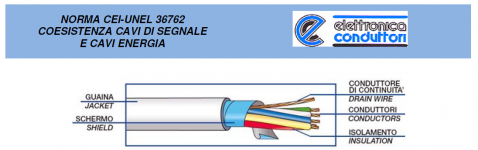
I intend to take out the Treble and Bass pots out from the PCB and connect them with shielded cable....
Assume the cable has 30pFd/foot, 100pFd per meter.
There is a 100pFd cap on the treble network. Carelessly throwing another 100pFd in here will mess-up the response. A few inches, 100mm, is probably fine.
- Status
- Not open for further replies.
- Home
- Amplifiers
- Tubes / Valves
- 12AX7 tone corrector + EL84 SE