I like the idea of a 2.5" tweeter. I think I've finally come up with a workable way of building the wrap-around 'teardrop' wave guide I've been wanting for my tweets (going with 5.3 Alpair 3").
A series of concentric circles drawn on plywood, connected with a spiral, and cut with a band saw at an angle. So, with one very long cut I get multiple circles for a stacked pyramid "trans-lam" kind of build and minimal waste.
A series of concentric circles drawn on plywood, connected with a spiral, and cut with a band saw at an angle. So, with one very long cut I get multiple circles for a stacked pyramid "trans-lam" kind of build and minimal waste.
Hi,
fun project.
Is a 2.5" crossed that low a good thing ? read here and there they was better above 800 hz XO and more ?
fun project.
Is a 2.5" crossed that low a good thing ? read here and there they was better above 800 hz XO and more ?
More than fine.
Resonant frequency is 117 Hz
as with many modern wideband drivers.
400 to 500 Hz is more than acceptable.
even at the min 200 Hz is acceptable.
once people stop forcing small drivers to do more
than the actual intended use. distortion goes away.
very simple concept.
Once your on a high pass, even at high power
distortion is low.
Your actually more likely to exceed the thermal rating.
800 Hz would be for older cheap paper cones
with small magnets and stiff accordion suspension
Since for the most part. most of them had resonant frequency
way up at 250 to 300 Hz
The nominal 1" XPS measures ~31/32" and the nominal 1/2" XPS measures ~9/16".
I probably have some 2" around somewhere if necessary.
Should I go ahead with the GRS-12PR-8, or wait for another turn on the crossover values? Again, novice about what non-primary specifications to look for, or where it matters.
R 5.6Ω __W __%
R 27Ω __W __%
C 15µF __V __%
C 27µF __V __% (qty 2 per)
C 56µF __V __%
L 680µH 181mΩ __V __A __% Air/Iron
L 1.5mH 389mΩ __V __A __% Air/Iron
L 6.8mH 501mΩ __V __A __% Air/Iron
I also have a set of PC83-4.
Sounds good whitedragon, I think you have a better grasp of the software then me.Correct.
Depends how your data is collected.
If your collecting microphone data on each driver center,
then yes you need to specify
its listening position.
you can do the same thing in the diffraction tool
depending on mic position.
otherwise yes correct it is rather important.
overall phase would be completely different
but actually it makes position change much easier
doing as you describe. if position needs to be changed.
Is a 2.5" crossed that low a good thing ?
Always used 3” (A5 is good choice). We use between 250-450 at the bottom
dave
Once your on a high pass, even at high powerdistortion is low.
Your actually more likely to exceed the thermal rating.
:^D
Well said. The whole point of a WAW. Get the beauty of a FR yet still have as much bass as you can “afford”.
dave
specifications to look for
Updated Crossover for 4 ohm PC68
These are suggested components for a low cost crossover.
R1 4 ohm PEpart # 004-4
C1 47uF PEpart # 027-352
C2 15uF PEpart # 027-344
C3 100uF PEpart # 027-360
L1 .60mH PEpart# 257-040
L2 1.2mH PEpart# 257-050
L3 6mH PEpart# 257-850
people will increase gauge for coils at substantial cost
capacitors can use metalized polypropylene, again at very
increased cost.
That was quick.
Im working on some more detailed drawings for the cabinet.
I'll do something for 19mm ply and double baffle.
Your case take into account
1" and 1/2" XPS
AKA .96875" or 24.6mm
.5625" or 14.2 mm
there is gonna be a 2.6 liter chamber for wideband .707 Qtc
approx 140 /150 liter for 12"
believe Qtc is a intentional .9 ish
500mm x 800mm Baffle
250mm / 486mm woofer center
250mm / 682mm wideband center
dont hold me to driver centers yet.
will confirm
Have a feeling the XPS is 24mm or 24.5 mm and 14mm
could confirm.
Otherwise was using the imperial measurements you posted
31/32 and 9/16
likely manufactured to a metric
could confirm.
Otherwise was using the imperial measurements you posted
31/32 and 9/16
likely manufactured to a metric
That may be hard to reach if the GRS specs of Qts = 1.06 is accurate. 🙂approx 140 /150 liter for 12"
believe Qtc is a intentional .9 ish
Correct
LOL ...yeah pretty much
She gonna be a big girl.
Yeah they have nice collection of high Qts drivers.
Has that old school sealed fun.
I was playing around with some 8" too, that is what I was thinking
the 12" and 15" knock a good 1.3 ... Shhh lol
LOL ...yeah pretty much
She gonna be a big girl.
Yeah they have nice collection of high Qts drivers.
Has that old school sealed fun.
I was playing around with some 8" too, that is what I was thinking
the 12" and 15" knock a good 1.3 ... Shhh lol
Have a feeling the XPS is 24mm or 24.5 mm and 14mm
could confirm.
Otherwise was using the imperial measurements you posted
31/32 and 9/16
likely manufactured to a metric
Attachments
@CANNON-FODDER
I wasnt sure how you usually do XPS cabs
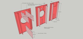
Have this design using both size materials
Overall gives volumes needed / WideBand Chamber/ Baffle position
Baffles easy numbers to find centers/ then after assemble gives a small 1mm
edge to trim. Bevel edges to taste, round - 45 degree etc
posted thumbnails - click to enlarge
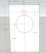
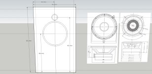
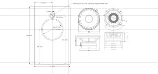
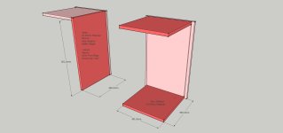


Hornresp has a very cool 2d wavefront simulator, where you can get a visual estimate on what diffraction effects would look like.
Thanks!
Backbrief: Interior dimensions
Woofer box: 751 x 451 x 460 (not counting front/back doublers)
WideBand box: (145-14.25) so ~130.75 x 130.5 x 170
Parts are here, main panels roughed out. Would have more done but the kids have strep so yesterday was mostly a wash.
Backbrief: Interior dimensions
Woofer box: 751 x 451 x 460 (not counting front/back doublers)
WideBand box: (145-14.25) so ~130.75 x 130.5 x 170
Parts are here, main panels roughed out. Would have more done but the kids have strep so yesterday was mostly a wash.
Question: The speaker appears to be configured for rear mounting with a front mounted foam gasket inside a raised lip of the frame. I wasn't tracking that was your intent.

It will be a day or two before I size the panels and start cutting the speaker openings.
If that area is significant and needs a XPS or some other treatment, please let me know.
Otherwise, if it's just a beauty ring, I am currently debating between
-- just removing the foam gasket - which leaves a trench there (assuming I recess it that depth).
-- cutting a foam ring at an angle (a door seal or something) and just gluing it in the track.
-- seeing if the Library printer could 3-D print a ring that size.
Sorry for the delay, I never built one this big, so I didn't anticipate needing to rip and glue up the 1" panels (I had sized them out before, but because they are pre-scored at 16", 24", 32" I just didn't want to trust filling those cuts, so I cut them out). And since I only have one spot suitable for those panels, that's 6 days. I could probably get the top/bottom out of a 2'x2' project panel but since I have to do the sides anyway, no reason not to use what I have.
I assumed flush mounting to the baffle.
Which is just a more common modern way to do things.
Some just mount flush and call it a day.
Others countersink the edges so the gasket sits flush with the baffle
Which is just a more common modern way to do things.
Some just mount flush and call it a day.
Others countersink the edges so the gasket sits flush with the baffle
It can be a reasonable option to rear mount and radius the baffle edge. Historically, rear mounting is often for horn mounting and rear mounting a direct radiator was considered worse than front mounting. Nowadays it's generally accepted that with a radius and perhaps careful shrouding over part of the surround it can be done well.
- Home
- Loudspeakers
- Multi-Way
- 12" Woofer and 2.5" Wideband Cabinet Conception / Crossover

