And I have a bridge to sell you. I picked up a couple step up wall transformers a while back, if you got 1/4 the power out that was claimed you were doing good. Then again I only paid $2 for them and was not expecting much. When I saw these all I hoped for is for them to be able to power a couple of signal tubes. It would have been nice to have a bit more voltage, we'll see how things pan out.
Actually just looked up the listing, not the one I have.
http://www.ebay.ca/itm/280758843245?ssPageName=STRK:MEWNX:IT&_trksid=p3984.m1439.l2649
Says mine is good for 5W.
Last edited:
They are now selling at Wal-Mart, AutoZone, etc with a rating of 200W continuous, 300W peak for less than $10.
Ok I am convinced this is the way to go. I have been spinning my wheels getting the stuff to work that I have. I am sure my transformer is not right for the job for one. I have tried the 555 timer going directly to a mosfet I pulled from the dead 80 watt 12 volt unit, also tried 555 timer into an LM386 to drive the mosfet. No change was noticed. I also ran the test signal to a transistor to switch the input, still no change. All produced the same output voltage. This time I used a small power transformer but could only get 26 volts from the 14 volt source. Even changed the frequency from 35 Hz to 100 Hz to 400 Hz. I have consumed hours on this thing. So after looking at the $5 220 volt power plug I am going to try one. I could always use a doubler if need be to get more volts. I will let you know after it arrives, thanks for the link.
I've hacked apert the cheap inverters. They run at about 30KHz. 240 volt versions give about 320VDC before the H-bridge. I've always found they don't complain or shut down if you remove the H-bridge fets. Add a small value poly cap across the DC reservoir to filter out some of the 30KHz hash and you're away.
And I have a bridge to sell you. I picked up a couple step up wall transformers a while back, if you got 1/4 the power out that was claimed you were doing good. Then again I only paid $2 for them and was not expecting much. When I saw these all I hoped for is for them to be able to power a couple of signal tubes. It would have been nice to have a bit more voltage, we'll see how things pan out.
Actually just looked up the listing, not the one I have.
http://www.ebay.ca/itm/280758843245?ssPageName=STRK:MEWNX:IT&_trksid=p3984.m1439.l2649
Says mine is good for 5W.
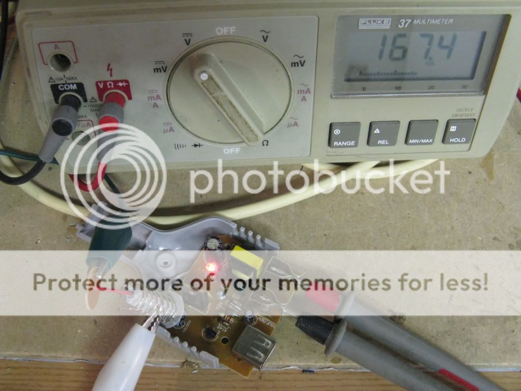
This little guy is actually putting out 167Vdc. I would have liked higher but it is good enough for what I want it for.
I just remembered one of the first tube amps I built,IIRC it used a 1U4 and/or a 3S4? (not sure) And I used the flash circuit from an old disposable camera for the HV. It ran from a couple of C cells,and had enough volume to be listenable in a small room,with a small speaker. Just a random tid-bit from the dusty vaults of my mind. 🙂
The inverter setup is a good way to go,I think.
In the pic in post #36,it looks like it's just a simple one transistor oscillator setup..with the transformer secondary connected straight to the output? No H-bridge or anything? Does it run at 60Hz,or ~60khz? 😕
The inverter setup is a good way to go,I think.
In the pic in post #36,it looks like it's just a simple one transistor oscillator setup..with the transformer secondary connected straight to the output? No H-bridge or anything? Does it run at 60Hz,or ~60khz? 😕
In the pic in post #36,it looks like it's just a simple one transistor oscillator setup..with the transformer secondary connected straight to the output? No H-bridge or anything? Does it run at 60Hz,or ~60khz? 😕
No, just DC out.
Why all the fancy crap? Just need a 24vct secondary dual primary transformer, two transistors, a couple of caps and resistors set up in push pull monostable oscillator 400Hz works fine. Built one for my old car CD ignition to generate the high voltage for the spark circuit. Feed +12 to the center tap and the transistors to ground on each leg. Cap and resistor back to base of other transistor off transformer connection of each leg.
Doc
http://upload.wikimedia.org/wikipedia/commons/6/6a/Transistor_Multivibrator.svg
Like so. sub transformer windings for R1, R4 and tie R2,R3 to CT with the +12 on it. Cap resistor RC control freq. Use 3055's and maybe this transformer:
24V CENTER TAP (12-0-12)2A TRANSFORMER-MPJA, Inc.
p.s. Add a phase shift cap for third leg and it will drive a surplus 400Hz 120V three phase blower. Great for old VW bus owners.
Last edited:
Why all the fancy crap? Just need a 24vct secondary dual primary transformer, two transistors, a couple of caps and resistors set up in push pull monostable oscillator 400Hz works fine. Built one for my old car CD ignition to generate the high voltage for the spark circuit. Feed +12 to the center tap and the transistors to ground on each leg. Cap and resistor back to base of other transistor off transformer connection of each leg.
Doc
http://upload.wikimedia.org/wikipedia/commons/6/6a/Transistor_Multivibrator.svg
Like so. sub transformer windings for R1, R4 and tie R2,R3 to CT with the +12 on it. Cap resistor RC control freq. Use 3055's and maybe this transformer:
24V CENTER TAP (12-0-12)2A TRANSFORMER-MPJA, Inc.
p.s. Add a phase shift cap for third leg and it will drive a surplus 400Hz 120V three phase blower. Great for old VW bus owners.
It was much easier for me to just hit the Buy button and open the package when it got here. If it was any more expensive I would have just run a 12v transformer backwards off my power supply. Probably should have but I was curious.
DIY doesn't have to mean each and every part is made from raw materials. Good switchmodes are beyond most people here, and can be a pain to make even for those in the know. They are just one piece of the jigsaw for many of us.
Gosh, and here I thought the whole point of this site was DIY, not BUY.
DIY tubes, capacitors, resistors, sockets? I don't like such DIY...
I am searching for chassis/case from some mass produced Chinese amp, but still can't find what I like. Otherwise it would be very nice to have such donors for DIY! 😉
If you own a hybrid car, you could carefully! tap the big battery, though it may be too much voltage, like 600VDC, at high amperage, so be VERY careful.
To each his own. You have seen the vid of they guy that makes his own tubes and then makes a radio out of them? I wound my own transformers, how could people actually BUY them when they could make them themselves?Gosh, and here I thought the whole point of this site was DIY, not BUY.
Doc
I have three amplifiers on the bench right now in different stages of completion and a number in the design stage. I have a small SS amp that I wanted to throw a tube front end on. I guess I could chase down parts which would cost me more than the ready made unit that I bought but then I would have to spend time figuring out how to best make it and spend time away from the projects I want to work on.
I do not know how I will ever be able to use this amp out in public knowing that there is a bought item in it. Oh wait, I only made the preamp section of it anyway, I had a small car stereo amp that I was not using and I stuck it in the cabinet so I could have a portable amp (run by a 12v gel cell).
Does that mean I get kicked off the forum?
Should you not put your DMM in AC mode? 😕Well it arriveth. No time to play but I had to see if it works. Quick test no load with 12.3V. 167V
I post a simple valid circuit that is cheap and easy to built and nobody says a word except one guy who says it's easier to buy it. I respond to him and four people jump my case. I was actually trying to teach something. My mistake.
You guys really need to reassess your priorities.
Doc
You guys really need to reassess your priorities.
Doc
Last edited:
I was checking it out, I might actually try it, if I have all the parts.
I guess this is like the "vibrator" power supplies that the HAM's would use?
I guess this is like the "vibrator" power supplies that the HAM's would use?
I was checking it out, I might actually try it, if I have all the parts.
Thanks. I think you will be very pleased. They are very reliable.
I guess this is like the "vibrator" power supplies that the HAM's would use?
Don't know what the Hams are using, but old tube car radios actually used a device called a multivibrator, which was essentially a high speed relay made to vibrate and supply pulse DC into a primary of a transformer to simulate AC. (The transformers didn't care.) You can build a pseudo vibrator with any multi-contact relay. Just power the relay through one of its own contacts. Put a supression cap across the points or it will eat them quickly.
Sorry, hadn't had my coffee yet. Yes, it is a multivibrator design.
Doc
Last edited:
I remember making such an inverter years ago (1968?) basically like this:
12V to 120V Inverter
It used smaller caps for a higher frequency of operation, and was housed in a cardboard tube with Al foil covering the ends. A micro-switch mounted on the bottom kept it turned off until someone picked it up. It used a very small transformer for little power transfer.
Looks like I type slower than you.😱
- Status
- Not open for further replies.
- Home
- Amplifiers
- Tubes / Valves
- 12 volt to 300 volt inverter question for tubes