You can avoid the cathode bypass of C3o with heater bias, but you can not eleminate all caps in the signal path. The last power supply cap is in the signal path and you can not combine direct coupling with filament bias of the power tube. From my experience sounds a high value gridstopper much worse than a good cap
What’s heater bias? Never heard of that before.
A choke can be inserted between the last power supply cap and the output tube, correct?
Wouldn't this minimize / eliminate the sonic impact of the last power supply cap in the signal?
Also, I am not using a grid stopper in my design, so this is not an issue.
Wouldn't this minimize / eliminate the sonic impact of the last power supply cap in the signal?
Also, I am not using a grid stopper in my design, so this is not an issue.
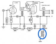
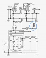
Here are 3 examples (see attached) from Thomas Mayer's designs that illustrate the choke after the last cap.
Regarding the gridstopper, I have been using my amps without them successfully. Am I missing something?
Regarding the gridstopper, I have been using my amps without them successfully. Am I missing something?
Attachments
Cag - In the other thread regarding heater bias, you state "I have connected the positive terminal of the Rod Coleman regulator to one side of the heater and the other side of the heater is connected to the cathode. From there a common resistor goes to signal ground. The negative terminal of the Rod Coleman regulator is connected to the signal ground."
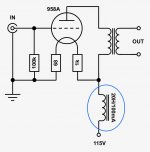
Please see the schematic below. For my C3g (triode), is this correct for heater bias?
Please see the schematic below. For my C3g (triode), is this correct for heater bias?
Attachments

C3g have 370ma heater current. I would choose 3,5V bias so 3.5V/ 0.37 = 9.5 ohm. I would use minimum 5Watt resistor. Plate voltage 200V@ 10ma
Hello.
What is the frequency response, especially the treble with the pentode control.
Piotr
I have not measured the frequency response but heared no downsides in high frequencies.
The problem is all look at the miller of power tubes, but for example a triode strapped D3a driver have far more miller capacitance than every power tube
I need help. So, my monoblocks have significantly (audible) different output voltages. This is easily heard. The measurements are below:
Channel A:
Output (at speaker terminals on monoblocks): 0.209Vac
B+ after LCLC: 423V
45B Plate: 409V
45B bias: 60.6V
45B Ik: 45mA
C3g Plate: 200V
C3g bias: -1.41V
C3g Ik: 14.5mA
Channel B:
Output (at speaker terminals on monoblocks): 0.142Vac
B+ after LCLC: 422V
45B Plate: 408V
45B bias: 60.3V
45B Ik: 45mA
C3g Plate: 183V
C3g bias: -1.40V
C3g Ik: 15mA
I tried swapping rectifier tubes, C3g tubes, 45B tubes, RCA input cables, speakers, pre-amp, source, etc. Every time I did the swap, the output voltage variance stayed with amps. In other words, Channel A monoblock always has the higher output voltage. What I don't get is that Channel A has the higher output voltage, yet it also has the higher C3g plate voltage. I would have that that the higher output voltage would align with the higher C3g plate voltage.
Anyways, this is clearly audible and I just can't figure out what could be causing this. Thoughts???
THe input voltages are equal. While making some measurements, I must have tweaked a possible wire crossover or bad solder. Now, without knowing why, the outputs are the same. More to come.
Right now I have 10Y in filament bias driving 2a3 outputs. Very nice too. You will need some kind of step-up for the gain. I'm using a Hammond 1140-LN-C broadcast transformer in 1:4 and it sounds pretty good. It was surprisingly cheap as well so I bought 2 more pairs.
Things you will need to consider for the 10Y is a good size heatsink for Rod's regs (now V9) and where to put it. And where to put the cathode resistors. They get hot, and I had to move them to the top of the chassis.
The 10Y stage I've built is for a Pass F4 input for a friend, and doesn't need a step-up. With the 1140 SUT in 1:4 I will need at least 10V bias for my own use, so I'll rebuild it with a different operating point. My present B+ is 282V and anode resistor is 15K but the B+ needs to go higher for 10V on the cathode.
I've also built a 112A and a 46 stage in filament bias, both good. The 10Y has the most inner detail - you will hear things that were hidden with other tubes. But the 46 has such good piano tone that I'm not sure I can live without it.
I attach the 10Y circuit I'm using, but this is to drive an F4 as said, so the circuit will be revised for the 2a3 amp. I'm using the 10Y at 6.8V and 1.2A filaments.
- Home
- Amplifiers
- Tubes / Valves
- 10Y (or other DHT) replacing a C3G driver