Yes. Maybe I have inadvertently confused the issue, by implying that A2 operation can happen without the extra supply. A2 operation can only work with the extra supply. A2 requires that the voltage of the grid be positive with respect to the cathode. But the cathode node is the voltage reference for the grid, so the grid can never by higher than the cathode. Can't even be equal. If you look at the loop that circulates through the grid, you will see a closed loop. It has to have it's own power source to circulate any current with this circuit.
All of the current from the main B+ (main current) supply goes through plate of the output tube. At the cathode of the output tube, some of the current returns to common through the cathode resistor, some through the driver tube. These are the only two paths, and must sum to the total.
The power to the driver tube has to go through the grid loop power supply, and it does increase the power dissipated by the FET, even with no grid current, because the FET has to drop more voltage. However, if the gyrator connection is used the extra supply does not influence the voltage at the cathode resistor. Remember the source resistor is a virtual current source, so the current source feeding the driver tube is outside the grid current loop, and the current returned to the B+ supply through the driver tube is not affected by the grid current. Therefore the current through the output cathode resistor is not affected.
However if the grid is connected at the plate of the driver tube, the amount of current delivered to the driver is reduced by the amount of current drawn by the grid, because the current source (source resistor) is enclosed inside of the grid loop, and the grid current must be subtracted from the total through the current source. The result is that this same increment of current must go through the output cathode resistor, because all of the current that returns to the B+ supply must go through either the driver or the output cathode resistor.
I'll attach the schematic with some example voltage values. I'm assuming the series supply is 100V. Remember the output tube is upside down from the usual, to make it easier to trace the current loops.
Hey Sheldon,
No its not your fault, I knew it coulnt possibly go A2 in the original configuration. It was one of the compromises that came up, I traded them in for simplicity and small and separated signal loops. Even now, i'm not shure I need A2. But more headroom to ensure that the ccs works (better) thats not bad. Back on topic:
Yesterday I blew up one 10m45s 😀😀 Nothing bad happens in the amp, just the music disappears, and a soft humming comes from the attached speaker.
It short circuits, which in my opinion is better than open. Especially for self induction spikes by choke and power supply transformer.
I blew it up when I was doing distortion measurements, and the multi meter attached to the anode of the 2a3 (525v) got into auto-power off mode. Without thinking I turned the knob of the multimeter to the off position, and then immediate back to V. I heard a little spike in the speaker followed by the aforementioned hum. 10 minutes later the ccs was replaced by a new one, and the amp played again. What I didnt expect was that I had to readjust the amp, (cathode potmeter on d3a) to trim the Va-2a3 back to 525v.
I guess there is some difference between them....
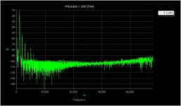
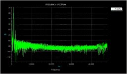
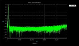
The distortion measurements were pretty good: 0.6% at 1watt; mostly 2nd.
Attachments
It's been fun. Summing up:
The FET wants a decent amount of voltage drain to source, in order to have a fairly constant input capacitance. I don't know what it is for this device, as it's not published. But if capacitance varies with level, distortion and phase shift will vary with level and frequency - usually an unpleasant form of distortion. Plus, the dropout voltage of the regulator means that you can't get very close to the full swing in A1.
That suggests the extra supply, regardless of intent to drive into A2.
If you have the extra supply, the gyrator connection makes the most sense.
Sheldon
Last edited:
- Status
- Not open for further replies.