....I should throw them on a curve tracer one of these days. It's about time the curve tracer at work gets to work at real manly voltages. We normally work in the 3.3 V world and 5 V often gets referred to as "high voltage". 🙂
~Tom
Those curves would be very interesting for me. In this amp, the drop over the second CCS is the bias for the 2a3. ( for schematic see my reply to Michael) Because its impossible to run in class A2, the dropping voltage minus the minimum voltage were the CCS still works (x2) is my maximum swing of the driver. It should be enough... but better to be shure.
Current settings: V drop-> driver CSS= 50v. I assumed about 5v for correct working of the CCS, so max swing would be 45v x 2= 90v pp.
With a mu of 4 of the 2a3 that gives me a theoretical max swing of 360v. Thats also were the 180v drop for the 2a3 ccs comes from...
gr. Paul
Thanx for the extensive reply!
I just measured it: its 80C😀 ; after playing from 5:30pm till 11:45pm.
It was the maiden voyage for the amp, and it sounds fantastic, much better then all my previous amps. Its the schematic from this post(http://www.diyaudio.com/forums/tubes-valves/158352-dcd-power-amplifier-2a3-d3a-ccs-coupled-new-topology.html#post2042587; just substitute the 2a3 for the 807. The d3a has 20mA current, and 175v Va.
It gave me goosebumps several times, and I had the impression that I heard Ella Fitzgerald standing right before me, and her sax player... very impressive.
But you are right, it is a little much for the poor ccs. I leave it for now, but I think I'm gonna back up just a little. I think 60mA/250v Va will be fine. it leaves me with about 3.5 watt max output power. The CCS has to drop 200v; but only 12 watts dissipation with 200v/60mA. And as a plus I would be able to use a TJ meshplate 2a3, I read great things about them.
The anti-triode setup: very interesting! I'm gonna try it sometimes, and see if I like it. But not in this amp, I would have to rebuild the case completely. There's only room for 2 CSS's on the heatsink, and that room is used up.
Greetz, Paul
I have done something similar to your schematic. I added a grid drive power supply connected from the cathode to the MOSFET drain (gets you to 0V or +V on the grid while providing good working voltage for the MOSFET), used the mu-output in order to source grid current, and also used a constant voltage "gyrator" circuit to avoid the output tube bias drifting much with driver tube drift. I'm working on a version right now that uses an anti-triode with parafeed output.
If you drop back to 60mA, you may have enough of a Rset resistance to try the anti-triode with a single 10M45. Just split the resistance into 2 halves and take the output from the center tap. Although with a 10K OPT primary you might not notice much. You should be able to go to 4K-5K with the CCS or anti-triode and down even more to ~3K with the anti-triode, if you happen to have any other OPTs to try.
Attachments
Last edited:
Hey Michael,
It is a 3k5 OPT; the 10k was a old philips OPT for the prototypes nr 1 till 3. Now I have the AE europe 3k5 OPT's; those are keepers, they sound really good...
gr. Paul
It is a 3k5 OPT; the 10k was a old philips OPT for the prototypes nr 1 till 3. Now I have the AE europe 3k5 OPT's; those are keepers, they sound really good...
gr. Paul
I have done something similar to your schematic. I added a grid drive power supply connected from the cathode to the MOSFET drain (gets you to 0V or +V on the grid while providing good working voltage for the MOSFET), used the mu-output in order to source grid current, and also used a constant voltage "gyrator" circuit to avoid the output tube bias drifting much with driver tube drift. I'm working on a version right now that uses an anti-triode with parafeed output.
If you drop back to 60mA, you may have enough of a Rset resistance to try the anti-triode with a single 10M45. Just split the resistance into 2 halves and take the output from the center tap. Although with a 10K OPT primary you might not notice much. You should be able to go to 4K-5K with the CCS or anti-triode and down even more to ~3K with the anti-triode, if you happen to have any other OPTs to try.
Michael, I thought about it, but I dont see why the splitting of the current setting resistor forces the ccs in anti triode mode. I know and understand that as I have it connected now, that the ccs keeps the current constant, and that current swaps between tube and OPT. In other words: the current through the OPT plus the current through the tube combined is the set current for the ccs. But I cant get my head around the split setting resistor... Any reads or explanation?
Other question with the anti triode setting: is the current "below" the 2a3 still constant, because the second ccs and the d3a tube V+ setting resistor (wich bleeds of any current not used by the d3a) rely on a constant current. It also makes sure there is no signal flowing through that resistor.
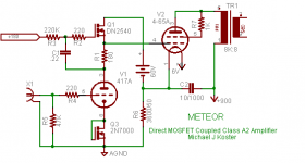
Also that "meteor" looks impressive; I dont have a clue how it works; wat does q2: current sink? or bias for the driver? q1 is a regulator? or ccs? And the 60v supply plus the drop of dn2540 is for the correct bias?
Last edited:
I am new at this but...see this article Class A 6AS7G PP for a ccs report by Larry Moore. If it makes sense to you, contact me because I need help executing a ccs in a 45 based amp I am tweeking.
John
John
Also that "meteor" looks impressive; I dont have a clue how it works
Michael, smoking amp, wavebourne, and revintage, and a couple others here, come up with designs that make my head hurt. Not because I don't like them, just because it takes my some time to figure out half of what is going on. I can figure out the individual elements, but putting them all together strains me.
wat does q2: current sink? or bias for the driver?
In this case, with gate tied to drain, Q3 is just set up as a constant voltage bias source. Sort of a quiet zener.
q1 is a regulator? or ccs? And the 60v supply plus the drop of dn2540 is for the correct bias?
Sorta neither, sorta both. At DC it functions as a source follower and will set the plate voltage at a couple volts above the bias supplied to the gate. So it's sort of a voltage regulator, but not a very stiff regulator. (The 60V supply is not part of the bias. I think Michael puts it on top the output cathode resistor as a fail safe mechanism to keep the output grid from going too high, say during startup. Michael?)
However, C1 bootstraps it across the plate resistor. So at AC, it maintains a constant voltage across R1, making R1 look like a current source to the driver tube. However, when the grid of the output tube draws current, the FET supplies the extra current, still looking like a current source to the driver tube, but a voltage source to the output tube.
OK, my head is starting to hurt.
Sheldon
Meteor:
Q3, as Sheldon points out, is used as a constant voltage diode. It's handy because it drops about 2.8V, more than LEDs but less than zeners, in a TO-92 package. Think of it as a 2.8V zener diode.
Q1 is the heart of this design. It's what parallels your (Paul) "CCS coupling" but as a gyrator instead of a CCS. A gyrator holds DC voltage constant like an inductor, and has high AC impedance like an inductor. What a gyrator can't do is store energy like an inductor, so the voltage can't go above the power supply voltage (like an inductor can). That's where the 60V supply comes in. It allows the gyrator to swing up to and above cathode voltage (which is a limitation in Paul's CCS coupling scheme.
The reason the 60V supply is based at the cathode is so that all the grid current (in class A2) goes straight back to the cathode, and out of the rest of the circuit. Taking the output of the gyrator from above the resistor (analogous to Rset in a CCS) is the so-called mu-follower and gives the output the low impedance of a source follower. This provides a high current drive capability to the power tube grid (class A2 again) but gives the driver tube a high impedance flat load line to maximize gain and minimize distortion. Grid current is not seen at all by the driver, only by the MOSFET and the 60V supply. Even if you weren't going class A2 with positive grid drive, the power supply is helpful to provide Vds working voltage to the MOSFET.
Anti-triode:
You already understand the CCS circuit operation where signal current is cyclically passed between the tube and OPT. Now imagine the load connected to the top of Rset (mu-follower case) now the signal current goes between the MOSFET and the OPT and the tube operates on a flat load line (as in the Meteor driver).
If the load is connected midway on Rset between tube and MOSFET, the tube and MOSFET each will "see" approximately 1/2 the load. As the tube current increases, the voltage drop across the bottom half of Rset increases, which makes the MOSFET gate more negative. This causes the MOSFET current to decrease, which reduces the voltage drop across the top half of Rset, until the total voltage drop across Rset is the same as at quiescent conditions. More current sunk from the load into the tube, less current sourced into the load from the MOSFET, in approximately equal and opposite amounts (hence anti-triode).
It's actually a push-pull circuit! Also known topologically as a totem pole.
The tube "sees" a load impedance 2X the actual load, because the MOSFET is driving half the current. Your 3.5K OPT will look like a 7K OPT to the tube, and damping factor, voltage swing, power, and linearity all improve.
I suppose it would be good to make up some current loop diagrams to illustrate this. It's not that difficult; just not the way we are used to thinking.
One more point. For the anti-triode to work well, Rset needs to be somewhat large relative to 1/gfs (the source resistance of the MOSFET) or there will be some loss of current swing and linearity on the MOSFET side. 1/gfs is approximately 5 ohms for a 10M45 at 50-60 mA and the 10M45 needs about 40 ohms Rset for this current. This will work OK in your case. There is another connection I use with an additional resistor and capacitor if Rset is too small.
Cheers,
Michael
Last edited:
Sheldon and Michael,
Thanx for educating me...
Sheldon, you say that the 60v supply doesnt do anything for the bias. As I see it now, its the main part of the offset between grid and cathode, which as far as I know IS the bias voltage. The current flowing through the cathode resistor (R6) puts it at a few hunderd volts (how much is the current Michael?) and the 60v are reversed polarity from that, and push back the voltage with 60v. The gyrator as I understand has similar characteristics as an induction, so low dc resistance, and thus low dc voltage drop. So DC voltage difference between cathode and grid = Vbias = 60v + Vds q1. Correct me if i'm wrong.
Ooops! I correct myself... The 60v isnt reverse polarity so the Vbias is Vds-60v. Now I understand the extra headroom Michael was talking about...hmmm really smart. I'm gonna look into my own schematic, and see if I can use this trick...
Anti-triode, I have to draw that current schematic to really understand it. Still is difficult for me to see whats happening there..
Sheldon and Michael,
Thanx for educating me...
Sheldon, you say that the 60v supply doesnt do anything for the bias. As I see it now, its the main part of the offset between grid and cathode, which as far as I know IS the bias voltage. The current flowing through the cathode resistor (R6) puts it at a few hunderd volts (how much is the current Michael?) and the 60v are reversed polarity from that, and push back the voltage with 60v. The gyrator as I understand has similar characteristics as an induction, so low dc resistance, and thus low dc voltage drop. So DC voltage difference between cathode and grid = Vbias = 60v + Vds q1. Correct me if i'm wrong.
Ooops! I correct myself... The 60v isnt reverse polarity so the Vbias is Vds-60v. Now I understand the extra headroom Michael was talking about...hmmm really smart. I'm gonna look into my own schematic, and see if I can use this trick...
Anti-triode, I have to draw that current schematic to really understand it. Still is difficult for me to see whats happening there..
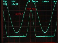
The 60V supply (actually running about 100V, consists of a toroid, a bridge, and a cap) doesn't set the bias, it just takes the MOSFET drain more positive to allow the driver plate to swing more positive. It also sources the grid current for A2 operation. In this amp I have driven the 4-65A grid 300V P-P while sourcing 50mA peak grid current.
The gyrator does have a voltage drop from the MOSFET drain to the plate/load. The low voltage drop, and where the bias is set, is from the "+180" input which is actually about -70 from the cathode. The cathode is about +250V with quiescent current of about 70mA on the 4-65A. I also needed to go to about +1050 on the B+ at the end of the day for enough plate dissipation and full output of 20W.
Paul, if the amp is still as shown in the other thread, you can simply insert the power supply (even as low as 24V if you have one) between the output tube cathode and 10M45 drain pin. Once you have this, another thing you can do for mild class A2 is connect the power tube grid to the top of Rset instead of the bottom (leaving the D3A plate connected as is). Between those and tapping the output Rset for anti-triode there are some simple things to try. I'm not sure how much voltage swing you can get with the power supply voltages as they are, though.
Attachments
Last edited:
Paul, if the amp is still as shown in the other thread, you can simply insert the power supply (even as low as 24V if you have one) between the output tube cathode and 10M45 drain pin. Once you have this, another thing you can do for mild class A2 is connect the power tube grid to the top of Rset instead of the bottom (leaving the D3A plate connected as is). Between those and tapping the output Rset for anti-triode there are some simple things to try. I'm not sure how much voltage swing you can get with the power supply voltages as they are, though.
OOPS if you try drive your output tube to more voltage swing, you risk popping the top 10M45.
You could use the IXTP01N100D, which uses the same Rset value, but only rated for 25W at 25C. It would probably derate to 12W with a decent heatsink. 2 of these in parallel if you could do it would be good also.
IXTP01N100D Ixys MOSFETs
The 60V supply (actually running about 100V, consists of a toroid, a bridge, and a cap) doesn't set the bias, it just takes the MOSFET drain more positive to allow the driver plate to swing more positive. It also sources the grid current for A2 operation. In this amp I have driven the 4-65A grid 300V P-P while sourcing 50mA peak grid current.
The gyrator does have a voltage drop from the MOSFET drain to the plate/load. The low voltage drop, and where the bias is set, is from the "+180" input which is actually about -70 from the cathode. The cathode is about +250V with quiescent current of about 70mA on the 4-65A. I also needed to go to about +1050 on the B+ at the end of the day for enough plate dissipation and full output of 20W.
Paul, if the amp is still as shown in the other thread, you can simply insert the power supply (even as low as 24V if you have one) between the output tube cathode and 10M45 drain pin. Once you have this, another thing you can do for mild class A2 is connect the power tube grid to the top of Rset instead of the bottom (leaving the D3A plate connected as is). Between those and tapping the output Rset for anti-triode there are some simple things to try. I'm not sure how much voltage swing you can get with the power supply voltages as they are, though.
I'm still not shure I'm getting the meteor completely...
But give me a hint when i'm right, and otherwise laugh about that stupid dutchman..😀 But i'm stubborn, I want to now that I understand it the right way, because its such a non standard design, and those are the ones you learn the most from.
So lets see. You chose the setting point for the driver tube, and decided for 180v on plate. Then you decided for 70 ma powertube current, and for that you needed 70v bias. So you had to have 250v on cathode, if you wanted dc coupling. you wanted to drive the grid of the powertube with a low impedance and decided to use a fet. because you had only the 70v bias as working (upswing) voltage, you decided to add the 60v powersupply. Now you had 70+60v=130v headroom.
Am I right?
I'm still figuring out how the constant voltage gyrator works, but you told me it compensates for the Va drift of the drivertube?
As for my amp, if i'm inserting a powersupply on the spot you said, it would be directly in my signal loop. Wouldnt it degrade sound quality?
The other tips are worth exploring, and the power supply voltages are easy to enlarge. my power transformer has not only 2x 250v (500v CT) but also 600v CT and 760v CT. My elco's are 2x220uF /450v in series, so I have some headroom...
And for the anti triode: I still have prototype nr3; the 807 triodes sounded best on a 10k load, unfortunately it left me with 0.8 watts, however fine sounding. If I use the anti triode, I could probably use some 4k pp toroidals...
You chose the setting point for the driver tube, and decided for 180v on plate. Then you decided for 70 ma powertube current, and for that you needed 70v bias. So you had to have 250v on cathode, if you wanted dc coupling. you wanted to drive the grid of the powertube with a low impedance and decided to use a fet. because you had only the 70v bias as working (upswing) voltage, you decided to add the 60v powersupply. Now you had 70+60v=130v headroom.
Am I right?
I'm still figuring out how the constant voltage gyrator works, but you told me it compensates for the Va drift of the drivertube?
I'll try to explain, and Michael can sort us both out if I miss. And if it seems overly simplified, that's just because I'll confuse myself otherwise.
Let's start with the output tube, cause that's the best place to start the design. At 1kV B+ Michael wants a current of 70mA. With that output tube (OT), the bias required is -70V.
Now, he wants to run the driver at around 160V on the plate, at around 10mA (guessing at these values, but it illustrates the point). Having decided on the gyrator and a 180R beneath the gyrator, that means about 180V to the grid of the output tube.
The FET is a depletion device, so to keep the numbers simple, let's say it requires a bias voltage of -2V. Therefore, to get 180V at the source (to the OT grid), we need to have the gate bias supply at 178V (it's actually 180 on Michael's schematic, but you only need to remember that there is a small negative difference between the gate and source voltage. You could use a MOSFET here, and the difference would be a small positive number).
Remember that the OT needs -70V bias, so if the grid is at 180V, the cathode needs to be at 180 +70, or 250V. So we need a 3.6k resistor under the OT cathode. So far, so good.
Now, if we weren't going into A2, or the cathode were connected directly to earth, we could take the brute force approach and just power the driver with a separate 400V supply. That would give us plenty of headroom. But when the amp goes into A2, the grid current will push up the voltage at the cathode resistor, causing distortion. Feeding the grid back to the drain of the FET, creates a separate current loop through the FET that does not go through the cathode resistor. The extra supply is needed to supply the grid current in this loop. This loop has the added benefit of having the FET gate swing with the cathode, which keeps the voltage across the FET more constant. This should help linearize the FET (Clever fellow, Michael).
Since the cathode is at 250V and the grid of the OT is at 180V, it seems like you have almost all the voltage swing needed, so less than 60V would probably suffice, as long it it can provide the required current. Michael?
As for the gyrator: Remember, it looks like a voltage source at DC, because the DC output voltage is set by the supply to the FET gate. So the quiescent voltage to the tube is set by the FET gate supply. As the driver tube ages, current through it will change, but the voltage will stay constant. But at audio frequencies, the cap from plate to gate makes it look like a current source (high impedance) to the plate.
As for my amp, if i'm inserting a powersupply on the spot you said, it would be directly in my signal loop. Wouldnt it degrade sound quality?
No, it's not really in the signal loop. The cathode voltage is just a reference for this supply common. Yes, if the supply common is not done poorly, there could be noise at that point. But that same supply would cause a noisy common (ground) in any application. Voltage fluctuation in the supply will be seen at the drain of the FET. But the FET has good PSSR and will isolate this noise from the signal path. Of course the isolation is not perfect, so the supply has to have some reasonable filtering.
Sheldon
Last edited:
This loop has the added benefit of having the FET gate swing with the cathode, which keeps the voltage across the FET more constant. This should help linearize the FET (Clever fellow, Michael).
Oops, strike that comment (except for the part about Michael). I was mixing this up in my mind with another project. Since the cathode is bypassed (in this case to the B+ supply), there should be no AC at the cathode. So no effect on the voltage at the FET drain.
Sheldon
A few fine points on the grid supply, since that seems to be the most controversial ;-)
Sheldon pretty much sums it up. The grid supply needs to be enough voltage to support the peak grid voltage (in the Meteor amp that was about +50V) plus I like 30V headroom across the MOSFET at peak signal to keep the capacitance low. Low capacitance is good for drive linearity and power supply rejection.
I ended up with about a 100V grid supply, consisting of a toroid wired for 2:1 step down giving about 70VRMS no load, a 200V bridge rectifier, and a 1000uF/200V KMH cap. The high drain resistance of the MOSFET feeding into the low plate resistance of the 417A results in no audible hum. If there was a hum problem, I was planning to try a cascode of 2 MOSFETs for Q1.
Another thing, the 10-12 mA quiescent driver current is summed with the cathode current at the top of R6. If the cathode current is 80mA and the driver current is -10 mA (it's sinking current through the "60V" power supply) then the total through R6 is 70mA.
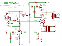
Not to stir things up too much, but here's another schematic which illustrates more of the same. This is what I've come up with based on the learning from the meteor amp and the spud 417A (another test amp). It's a work in progress so there may be some errors.
A 300B is operated with fixed bias and fixed anode voltage, going into grid current slightly at full signal (+20Vg). The 300B sees a 4K load line. The 300B would normally output 15W on this load line, but the anti-triode doubles this to 30W approximate Po.
The 300B has a gyrator anti-triode as it's plate load instead of a CCS, which I think might sound different based on previous experiments. I also will try a voltage clamp (zener string and 2N3055) instead of the cathode resistor. I also show the bias reference circuit, a DN2540 with a trimpot and a large load resistor.
Cheers,
Michael
Sheldon pretty much sums it up. The grid supply needs to be enough voltage to support the peak grid voltage (in the Meteor amp that was about +50V) plus I like 30V headroom across the MOSFET at peak signal to keep the capacitance low. Low capacitance is good for drive linearity and power supply rejection.
I ended up with about a 100V grid supply, consisting of a toroid wired for 2:1 step down giving about 70VRMS no load, a 200V bridge rectifier, and a 1000uF/200V KMH cap. The high drain resistance of the MOSFET feeding into the low plate resistance of the 417A results in no audible hum. If there was a hum problem, I was planning to try a cascode of 2 MOSFETs for Q1.
Another thing, the 10-12 mA quiescent driver current is summed with the cathode current at the top of R6. If the cathode current is 80mA and the driver current is -10 mA (it's sinking current through the "60V" power supply) then the total through R6 is 70mA.
Not to stir things up too much, but here's another schematic which illustrates more of the same. This is what I've come up with based on the learning from the meteor amp and the spud 417A (another test amp). It's a work in progress so there may be some errors.
A 300B is operated with fixed bias and fixed anode voltage, going into grid current slightly at full signal (+20Vg). The 300B sees a 4K load line. The 300B would normally output 15W on this load line, but the anti-triode doubles this to 30W approximate Po.
The 300B has a gyrator anti-triode as it's plate load instead of a CCS, which I think might sound different based on previous experiments. I also will try a voltage clamp (zener string and 2N3055) instead of the cathode resistor. I also show the bias reference circuit, a DN2540 with a trimpot and a large load resistor.
Cheers,
Michael
Attachments
Last edited:
Another thing, the 10-12 mA quiescent driver current is summed with the cathode current at the top of R6. If the cathode current is 80mA and the driver current is -10 mA (it's sinking current through the "60V" power supply) then the total through R6 is 70mA.
Ah yes, I tried to go step by step but still forgot to add that in. Thanks for reminding us.
Sheldon
A few fine points on the grid supply, since that seems to be the most controversial ;-)
Sheldon pretty much sums it up. The grid supply needs to be enough voltage to support the peak grid voltage (in the Meteor amp that was about +50V) plus I like 30V headroom across the MOSFET at peak signal to keep the capacitance low. Low capacitance is good for drive linearity and power supply rejection.
I ended up with about a 100V grid supply, consisting of a toroid wired for 2:1 step down giving about 70VRMS no load, a 200V bridge rectifier, and a 1000uF/200V KMH cap. The high drain resistance of the MOSFET feeding into the low plate resistance of the 417A results in no audible hum. If there was a hum problem, I was planning to try a cascode of 2 MOSFETs for Q1.
Another thing, the 10-12 mA quiescent driver current is summed with the cathode current at the top of R6. If the cathode current is 80mA and the driver current is -10 mA (it's sinking current through the "60V" power supply) then the total through R6 is 70mA.
Not to stir things up too much, but here's another schematic which illustrates more of the same. This is what I've come up with based on the learning from the meteor amp and the spud 417A (another test amp). It's a work in progress so there may be some errors.
A 300B is operated with fixed bias and fixed anode voltage, going into grid current slightly at full signal (+20Vg). The 300B sees a 4K load line. The 300B would normally output 15W on this load line, but the anti-triode doubles this to 30W approximate Po.
The 300B has a gyrator anti-triode as it's plate load instead of a CCS, which I think might sound different based on previous experiments. I also will try a voltage clamp (zener string and 2N3055) instead of the cathode resistor. I also show the bias reference circuit, a DN2540 with a trimpot and a large load resistor.
Cheers,
Michael
Hey Michael and Sheldon,
Looked in the forum this morning and saw a lot to read...nice!
Dont have time till tomorrow (sunday); have a whisky tasting session today😀😀😀
Michael, that new amp looks a bit like mine...but with discrete regulators and anti triode. Is the zener/transistor cathode thingy better sounding than a power resistor? How does the amp sound?
Mine is still using the "abused" ccs at 80C /100mA 180v. It sounds so good...
A friend who came listening wednesday wants to build one too... All kinds of shortcomings wich we wrote off to the speakers and pre-amp are solved.
So i'm a bit afraid of changing it now... fearing tampering will degrade sound quality. But I realize i will have to do it, in order to get its reliability up.
Tomorrow I will read all the posts, and let you now!
Now off to tasting whiskey!
Bye, Paul
Hi Paul,
That last amp is literally a work in progress; having torn down the Meteor amp, I'm reusing my breadboard parts for this one. It's not been reanimated yet so I can't comment on the sound.
The transistor thingy actually uses a HV darlington NPN (TV deflection driver). The 3055 was just a symbol I grabbed from my schematic library and would pop with 250V on it😱 That's highly experimental and I need to test it before recommending it.
With the anti-triode above the tube (totem pole circuit) the current at the cathode/OPT return node isn't constant anymore; you will have signal current and would need to bypass the resistor. In my schematic I just connected the OPT to ground so the tube signal current instead of anti-triode signal goes through the clamp. I'll probably try a bypassed resistor also and I'll let you know on the sound quality.
Not knowing the exact derating of the 10M45, you may be within the SOA even derating for an extra 55C of Tc. If the derating is 0.5W/C or less you may be OK at 18W... You could probably afford to wait and see.
So... Island, highland, or Speyside??? Open cask? Mmmm
.... And if it seems overly simplified, that's just because I'll confuse myself otherwise....
As for the gyrator: Remember, it looks like a voltage source at DC, because the DC output voltage is set by the supply to the FET gate. So the quiescent voltage to the tube is set by the FET gate supply. As the driver tube ages, current through it will change, but the voltage will stay constant. But at audio frequencies, the cap from plate to gate makes it look like a current source (high impedance) to the plate.
No, it's not really in the signal loop. The cathode voltage is just a reference for this supply common. Yes, if the supply common is not done poorly, there could be noise at that point. But that same supply would cause a noisy common (ground) in any application. Voltage fluctuation in the supply will be seen at the drain of the FET. But the FET has good PSSR and will isolate this noise from the signal path. Of course the isolation is not perfect, so the supply has to have some reasonable filtering.
Sheldon
Sheldon, thats no problem, the way you explain it makes me understand a lot of things I didnt get from looking at the schematic. Most of the schematic was clear for me already, but I missed some things. I'll have to restudy that part with the grid current adding to the cathode current. I realize now fully that a lot of things change when you go from A1 to A2. Its not only the driver which is loaded heavyer. Maybe its a good thing my amp isnt capable of A2, and for me it plays loud enough. (Its 4.7 watts)
A gyrator is a cool thing; and the application here is perfect. Michael has a fixed voltage cathode bias, but if I were to put a cathode potmeter instead of that, I think you could alter anode-current and Vbias, but not V-anode.
Sheldon, you know a lot more about tube circuits then me, but I think you're wrong about the powersupply inserting in the cathode circuit of the output tube; it is directly in the signal loop. In my amp that is; not in Michaels.
My ac signalloop in the output circuit consists of only the 2a3, the 8uF PIO, and the output transformer. If I put a powersupply in series with the cathode, (transformer->bridge rect.->electrolitic cap) my signal is forced to go through that capacitor. Or am I wrong?
Thanks anyway, for spending time on my stuff...
gr. Paul
Hi Paul,
That last amp is literally a work in progress; having torn down the Meteor amp, I'm reusing my breadboard parts for this one. It's not been reanimated yet so I can't comment on the sound.
The transistor thingy actually uses a HV darlington NPN (TV deflection driver). The 3055 was just a symbol I grabbed from my schematic library and would pop with 250V on it😱 That's highly experimental and I need to test it before recommending it.
With the anti-triode above the tube (totem pole circuit) the current at the cathode/OPT return node isn't constant anymore; you will have signal current and would need to bypass the resistor. In my schematic I just connected the OPT to ground so the tube signal current instead of anti-triode signal goes through the clamp. I'll probably try a bypassed resistor also and I'll let you know on the sound quality.
Not knowing the exact derating of the 10M45, you may be within the SOA even derating for an extra 55C of Tc. If the derating is 0.5W/C or less you may be OK at 18W... You could probably afford to wait and see.
So... Island, highland, or Speyside??? Open cask? Mmmm
Yes, please let me know, it would be a nice alternative for the large cathode resistors.
I realized the problem with the current not being constant anymore.
I wanted to have that, thats why I put 2 CCS's in my amp, the cathode resister sees no signal current, and you dont have to bypass it.
But your method has a LOT more efficiency. Dont know what will sound better though; I opted for as small, separated signal loops as possible, without looking at efficiency.
off topic:
😀 The whisky tasting was a great success. Because we (me and 2 friends) were a little bit sick of the overly commercial whiskey tastings we attended once a year, we do it at home now. Twice a year we choose 2 or 3 bottles from or own collection, and come together at one of our homes. So normally we have about 10 bottles to taste (they dont have to be emptied), but this year my friend had some small tasting bottles. So I thing we had about 23 different whiskeys.😱
glen morangie: 4 regular/ port/burgundy and madeirawood
bowmore: 4 ones from 12 till 21 years
3 separate ones I dont remember (I killed the braincell that stored that memory I think)
That were the small 0.2L flasks...
Normal 0.7L:
3 different glen rothes (special reserve, a 1972 one and a 14 y old special edition)
Té Bheag (one of my low cost favorites)
glen morangie: the new series; 2 of them (the one on souterne cask was gooood)
highland park: 18y old and a reissue 15y first edition cask strength.
Oh and we started with three different ones at the whiskey store: A highland park reissue which one of my friends bought, a 18y tomatin (who I should have bought), and one I dont remember...😀😀
To be honest, it were all very small samples, otherwise I would be dead...
We startet at 3:00 pm till 1:30 am the other day, so we took our time...
Greetings, Paul
Sheldon, you know a lot more about tube circuits then me,
Doubtful.
I think you're wrong about the powersupply inserting in the cathode circuit of the output tube; it is directly in the signal loop. In my amp that is; not in Michaels.
Ah, OK. Didn't catch the distinction the first time. I guess that you are referring to this:
Paul, if the amp is still as shown in the other thread, you can simply insert the power supply (even as low as 24V if you have one) between the output tube cathode and 10M45 drain pin. Once you have this, another thing you can do for mild class A2 is connect the power tube grid to the top of Rset instead of the bottom (leaving the D3A plate connected as is). Between those and tapping the output Rset for anti-triode there are some simple things to try. I'm not sure how much voltage swing you can get with the power supply voltages as they are, though.
So, yes, I think you are right about this:
My ac signalloop in the output circuit consists of only the 2a3, the 8uF PIO, and the output transformer. If I put a powersupply in series with the cathode, (transformer->bridge rect.->electrolitic cap) my signal is forced to go through that capacitor. Or am I wrong?l
BTW, could use a rechargeable battery for this, as long at it can take the standing current of the D3A. Might be fun to try.
Sheldon
- Status
- Not open for further replies.
- Home
- Amplifiers
- Tubes / Valves
- 10M45s: strange behaviour @ 100mA