Doubtful.
Ah, OK. Didn't catch the distinction the first time. I guess that you are referring to this:
So, yes, I think you are right about this:
BTW, could use a rechargeable battery for this, as long at it can take the standing current of the D3A. Might be fun to try.
Sheldon
😀 Thanks, but it isnt doubtful to me! I build a tube amp 22 years ago, a tube pre amp 20 years ago, and then 19 years of nothing, I just started diggin in a year ago. Most of the knowledge I posses is learning out of own interest and instinct; I only did a 4 year basic electronics education, aimed at producing repairmen. ("MTS" I really dont know if there is a equivalent in the US) PLUS you saw a lot more of the specifics of Michaels circuit...
The rechargeable battery is a good idea, but since it is put in the 2A3 cathode, I think it should be able to withstand 100mA? Wouldnt that current try to charge the battery wrong polarity? because to enlarge the voltage for the driver it should be inserted opposite polarity right? (dont want to let the battery explode😱)
As for inserting batteries in audio circuitry, has anybody ever sought out wat type sounds best? I know from my modelplane-hobby that NiCD's have the lowest resistance; just a few milli-ohms. But I dont know of high frequency specs, if they are better or worse than a capacitor...
greetings, Paul
My ac signalloop in the output circuit consists of only the 2a3, the 8uF PIO, and the output transformer. If I put a powersupply in series with the cathode, (transformer->bridge rect.->electrolitic cap) my signal is forced to go through that capacitor. Or am I wrong?
gr. Paul
Hi Paul,
I thnk you might be misunderstanding where to insert the power supply.
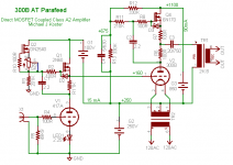
If you insert a power supply from cathode to the lower 10M45 drain,
*leaving the OPT and R4 connected to the cathode*
Then that power supply is not in the cathode circuit. It's only in the drain circuit of the lower 10M45, which is very well isolated from any signal path.
Also note that any grid current is sourced by this supply, which is returned to the cathode. No grid current appears anywhere else in the circuit, not even in the cathode resistor. Intentional A2 may not work well with a CCS anode load, but for occasional peaks it may be useful.
The driver current loops between your amp and mine are actually not that different except for the grid power supply; only the way you chose to draw your schematic showing the driver under the power tube differs.
So, yes you can insert the power sypply to get more voltage headroom; you don't have to go A2, and if you avoid anti-triode on the top CCS you can keep the resistor bias. Probably worth a try if you're in an experimental mood.
A couple of 9V batteries in series for 18V might be a quick test and would probably hold a charge for a few hours at 10mA. Put a reverse biased diode across them so you don't reverse voltage when they discharge...
Cheers,
Michael
PS I have decided to fix the overlapping current loops and go with stacked supplies, yet again...
Attachments
My only formal training in electronics consists of a basic college physics course - a long time ago. Everything else is from the last few years as a hobbiest, with a lot of help here.
Let's make sure we are on the same page. Here it is as I intrepret Michail's intent.
The battery (or supply) is in series with the driver tube, and only passes the current of that tube. The rest of the cathode current of the power tube circulates in a parallel path, through the power tubes cathode resistor. Of course, as in Michael's example, this requires the gyrator connection of the FET (that's not the right symbol for the depletion device, but it's all I had).
So if you are running the D3A at 10-20mA, I believe that NiCad (and maybe other types) will withstand a slight constant current over charge. You'd have to check the spec's. I think that others (maybe kevinkr) has tested various types as a cathode biasing device for small signal tubes.
Sheldon
Attachments
Last edited:
And, if your series supply is a little noisy, add a little Loftin/White style noise cancellation.
Noticed that Michael posted while I was writing. I haven't checked for conflicts, but if the responses aren't the same, go with Michael.
Also noticed that I have the battery connected with wrong polarity.
Noticed that Michael posted while I was writing. I haven't checked for conflicts, but if the responses aren't the same, go with Michael.
Also noticed that I have the battery connected with wrong polarity.
Attachments
Last edited:
I have the batteries connected backwards, and confused myself. In series, properly oriented, the current flows through the battery just like it would with multiple batteries in series. So no problem, except that they would draw down over time with A2 current - as Michael points out. I can't edit the drawings (too late), but if you reverse the batteries (or supplies), then I think it's the same as Michael's drawing. Also, Michael has pointed out that, although the current for the driver has to pass through the extra supply, it is isolated by the gyrator from the driver plate. So, it is not in the AC signal path after all.
Sorry for the confusion. I really should double check everything before I post. Then check again.
Sheldon
edit: Learning together here, Paul.
Sorry for the confusion. I really should double check everything before I post. Then check again.
Sheldon
edit: Learning together here, Paul.
Last edited:
OK. Shoulda done this in the first place. Here is the first schematic I drew, just rearranged. All the connections are exactly the same, except I oriented the extra supply (or battery symbol) correctly. Had I done this I would'nt have got lost myself, and confused the issue.
Couple of things to remember that may help.
1. Mentally simplify things by considering the connection node at the output tube cathode resistor as just another power supply. Now, it has relatively high output impedance. But that doesn't matter for the analysis. As long as the driver tube is fed by a current source, you can ignore the impedance, and even ignore the fact that it comes from the output cathode, because neither has a significant AC component. It's just a source of current.
2. Now, if you connect the driver FET as a gyrator, it still won't matter, as long as you don't draw grid current. With no grid current, the current through the FET is the same as the current through the drain resistor to the plate of the driver. Remember the gyrator looks like a current source to the plate. So if it sees the same current as the FET drain, then it looks like a current source to our ouput cathode power supply (just eliminate the grid connection for the analysis - it draws essentially no AC or DC current).
3. But the situation changes when grid current is drawn. That's where the extra supply comes in, and where the gyrator comes into play. Look at the schematic and you will see that the extra supply drives a current loop through the grid (in a figure 8 pattern on this schematic) from the drain through the grid, to the cathode, back to the source of the FET. Since all the extra current is contained in that loop, it has no effect on the voltage at the output tube cathode. As Michael noted, any ripple in this supply is blocked by high impedance of the FET drain, so it does not bleed through to the source.
Also as noted by Michael, the output cathode has a limited voltage, so the extra supply also provides some extra headroom. This is a benefit (audible or not, you decide) independent of grid current. But the supply is necessary in this design if you draw grid current.
Sheldon
Attachments
Last edited:
I have the batteries connected backwards, and confused myself. In series, properly oriented, the current flows through the battery just like it would with multiple batteries in series. So no problem, except that they would draw down over time with A2 current -
Should reword this, as it's misleading. The batteries would have to supply power whenever the amp is on, but extra current during A2 operation. So even without A2 the battery would drain during operation.
Sheldon
Should reword this, as it's misleading. The batteries would have to supply power whenever the amp is on, but extra current during A2 operation. So even without A2 the battery would drain during operation.
Sheldon
Sheldon, this is exacly as I understand it from Michaels hint. I was confused when you drew that supply upside down, because then it would decrease the headroom. As I see it, the way to best explain the workings of the extra supply would be: it lowers the bias voltage with a fair amount, so you have to use a larger supplyvoltage for the lower CCS to overcome this. The CCS doesnt have to be driven to the point were it stops working, but has some nice extra headroom.
It "feels" strange, that reverse polarity, and normally you have an external current loop to discharge a battery. But here its the current which flows in opposite direction through the battery which does the discharging.
Thats also why I was concerned; when its empty, that current tries to charge the battery reverse polarity; it will probably get really hot and explode.
Have some experience with batteries from my modelplane hobby.
But Michael was right (of course) , nothin a diode cant fix. But since this is not in the signal loop, and I had the powertranny made with a 40v ac 100ma for fixed bias, and I didnt use that until now, maybe I could rectify that one, put it in the circuit and see how it sounds.
Off topic:
Sheldon, ive said it before, but I'll say it one last time, incredible that you guys at the other end of the world spend so much time helping me improve my circuit. You even drew my circuit, I should have done that, but was to busy... or lazy😉
As a matter of fact, here at DIYaudio, when I look at some other posts I'm amazed how much time some people invest to help other people. I'm a computer engineer (microsoft😱 specialist) and if you see some of the forums there... People get impatient and pissed because somebody forgets to read a little thing, which according to there opinion they should have found on google...
Should reword this, as it's misleading. The batteries would have to supply power whenever the amp is on, but extra current during A2 operation. So even without A2 the battery would drain during operation.
Sheldon
The discharge current is (as I see it) the current which flows through the CCS.
If you connect the grid to the anode of the d3a, the extra current which goes into the grid at A2 is subtracted from Ia-d3a.
If you connect the grid from the 2a3 to the kathode (or drain) from the ccs, your story is correct. But I'm not really interested in using my amp in A2. Any extra current used by the driver circuit, is subtracted from the current going through the cathode resistor, and I want that current as constant as possible. Otherwise the 2a3 cathode isnt at a stable potential anymore.
For me the benefit in the extra powersupply is the extra voltage the driver ccs has to work with.
Paul
Last edited:
Hi Paul,
I thnk you might be misunderstanding where to insert the power supply.
If you insert a power supply from cathode to the lower 10M45 drain,
*leaving the OPT and R4 connected to the cathode*
Then that power supply is not in the cathode circuit. It's only in the drain circuit of the lower 10M45, which is very well isolated from any signal path.
Also note that any grid current is sourced by this supply, which is returned to the cathode. No grid current appears anywhere else in the circuit, not even in the cathode resistor. Intentional A2 may not work well with a CCS anode load, but for occasional peaks it may be useful.
The driver current loops between your amp and mine are actually not that different except for the grid power supply; only the way you chose to draw your schematic showing the driver under the power tube differs.
So, yes you can insert the power sypply to get more voltage headroom; you don't have to go A2, and if you avoid anti-triode on the top CCS you can keep the resistor bias. Probably worth a try if you're in an experimental mood.
A couple of 9V batteries in series for 18V might be a quick test and would probably hold a charge for a few hours at 10mA. Put a reverse biased diode across them so you don't reverse voltage when they discharge...
Cheers,
Michael
PS I have decided to fix the overlapping current loops and go with stacked supplies, yet again...
Yes I get it now, that place is insulated from the signal loops. I told in one of the posts above in an answer to Sheldon i'm gonna try it with the unused fixed bias tap on the transformer...
Nice idea, using 3 separate powersupplies; no more need for large power resistors. You gonna regulate all 3 of them? Or rely on the self regulating character of your amp?
And why "yet again"? You've done that before?
gr. Paul
If you connect the grid from the 2a3 to the kathode (or drain) from the ccs, your story is correct. But I'm not really interested in using my amp in A2. Any extra current used by the driver circuit, is subtracted from the current going through the cathode resistor, and I want that current as constant as possible. Otherwise the 2a3 cathode isnt at a stable potential anymore.
Even if you don't plan to use the amp in A2 (2A3 are claimed to work well in A2), you have nothing to lose with the gyrator connection. The current through the 2A3 cathode will be stable either way. I'd guess the gyrator connection will make a smoother transition into clipping. At any rate, easy to try both. Just one connection to change.
As far as the help goes; happy to do it. It's as much an intellectual exercise for me as is help for anyone else.
Sheldon
Dont know for shure, but I think the "gyrator" connection takes extra current out of the 2a3. I think it works like this: A CCS tries to keep the voltage over the setting resistor stable. If you connect it "above" the resistor, and snoop away some current, there would be a little less current flowing through the setting resistor. The voltage over the resistor drops, and the ccs compensates by delivering a little extra current. (just the amount snooped away) But that current comes from somewhere, and the only place it can come from is the current from the top 100mA CCS. But the current through the bottom ccs and the cathode resistor is combined that 100mA. So if you increase the current through the bottom CCS, there is a little less current going through the cathode resistor, and the voltage across it drops. But this is the 2a3 cathode reference voltage, wich shouldnt change at all.
Or am I wrong?
gr. Paul
Or am I wrong?
gr. Paul
Dont know for shure, but I think the "gyrator" connection takes extra current out of the 2a3. I think it works like this: A CCS tries to keep the voltage over the setting resistor stable. If you connect it "above" the resistor, and snoop away some current, there would be a little less current flowing through the setting resistor. The voltage over the resistor drops, and the ccs compensates by delivering a little extra current. (just the amount snooped away) But that current comes from somewhere, and the only place it can come from is the current from the top 100mA CCS. But the current through the bottom ccs and the cathode resistor is combined that 100mA. So if you increase the current through the bottom CCS, there is a little less current going through the cathode resistor, and the voltage across it drops. But this is the 2a3 cathode reference voltage, wich shouldnt change at all.
The gyrator connection makes virtually no difference if the grid does not draw current, whether an extra series supply is used or not. But in the case of grid current, remember, we are only talking about the situation where the extra supply is used. In that case, the extra current comes from the added supply and circulates in a closed loop from grid back to the FET source (trace the loop from the positive positive battery terminal on the schematic, back to its negative terminal). It does not change the current drawn from the output tube cathode. So no voltage change will be seen there.
Sheldon
Last edited:
The gyrator connection makes virtually no difference if the grid does not draw current, whether an extra series supply is used or not. But in the case of grid current, remember, we are only talking about the situation where the extra supply is used. In that case, the extra current comes from the added supply and circulates in a closed loop from grid back to the FET source (trace the loop from the positive positive battery terminal on the schematic, back to its negative terminal). It does not change the current drawn from the output tube cathode. So no voltage change will be seen there.
Sheldon
You are right, I see it now... without the extra powersupply the grid voltage is impossible to become more positive then the cathode (I should know, I designed it that way🙄).
And because the only higher potential available is the extra powersupply, its quite obvious the current comes from that. You can see it best if you trace the current path like you said. All in all its quite an elegant solution... I'm gonna try it when I have some spare time. I wonder if I have to regulate the extra powersupply, because if it has to deliver current, its voltage will slightly drop. That influences directly the bias of the output tube, dont know if the effect will be negligable...
Paul
I wonder if I have to regulate the extra powersupply, because if it has to deliver current, its voltage will slightly drop. That influences directly the bias of the output tube, dont know if the effect will be negligable...
No, it has no influence on the bias of the output tube. Fluctuation in the voltage of this supply will not be seen at the output cathode resistor, because fluctuation of current in the extra supply will not be seen there. Fluctuation in voltage of the extra supply will be seen at the drain of the FET, but as mentioned before, this is isolated from the output grid and driver plate, by the FET. So, if the supply is reasonably sized, with adequate capacitance, regulation should be unnessary.
BTW, to make it easy for everyone who might be auditing our discussion, I've redrawn the schematic to make it even easier to see the current loops. I just took the output section and turned it upside down. Also added the main power supply (battery symbol between ground and output CCS). Sometimes a different view makes it easier to follow. It does for me.
Attachments
Let's simplify further to better illustrate:
The cathode of the output tube can be seen as just another power supply. It's a high impedance supply, so a current change will cause a voltage change.
No extra supply, no grid current:
In the first figure (left to right), think of the battery symbol as the cathode resistor supply. The current is set by the current source (model for the driver tube and CCS).
Extra supply:
In the second figure, add a series supply. Note that the current through this loop hasn't changed, so even if the first supply is high impedance, there will be no change in voltage across that supply. Now, let the top supply voltage vary - still no change in current, so the voltage across the bottom supply cannot change.
Extra supply with grid current:
Add a resistor to the connection between the supplies and the top of the current source (model for current flow through the output grid). Now current flows in the top loop, controlled by the resistor. Now the top supply carries the original current, plus the current through the resistor. But the only path for current to return to the bottom supply, is through the current source, so the amount of current flowing through the bottom supply is unchanged. Therefore, no change in the voltage across the bottom supply.
Sheldon
Attachments
Last edited:
Let's simplify further to better illustrate:
The cathode of the output tube can be seen as just another power supply. It's a high impedance supply, so a current change will cause a voltage change.
No extra supply, no grid current:
In the first figure (left to right), think of the battery symbol as the cathode resistor supply. The current is set by the current source (model for the driver tube and CCS).
Extra supply:
In the second figure, add a series supply. Note that the current through this loop hasn't changed, so even if the first supply is high impedance, there will be no change in voltage across that supply. Now, let the top supply voltage vary - still no change in current, so the voltage across the bottom supply cannot change.
Extra supply with grid current:
Add a resistor to the connection between the supplies and the top of the current source (model for current flow through the output grid). Now current flows in the top loop, controlled by the resistor. Now the top supply carries the original current, plus the current through the resistor. But the only path for current to return to the bottom supply, is through the current source, so the amount of current flowing through the bottom supply is unchanged. Therefore, no change in the voltage across the bottom supply.
Sheldon
Sheldon, sorry, it drives me crazy!
All my instincts cry WRONG! Tonight I have some real time to look into it; wifey is out tonight😀
I'm drawing like crazy... and the more I draw the more confused I get. 😕
I made a drawing with voltages in it in A2 state. There is an asumed 2mA grid current running, and the CCS set for 20 mA. If I connect it the standard way (anode d3a) there is only 18mA left for the driver. But were does all the current come from in this state? if its from the extra supply, does the "resistor supply" deliver any current at all? because if not, then 100mA will flow through the cathode resister, voltage will go up.
If you connect it the gyrator way, its even more difficult.
I will just have to try it, and put an oscilloscope on the cathode resistor, force it into a2 and see wat happens. I'm not smart enough to reason myself out of it.
I can follow your explanation, and with the 3 simple drawings it looks okay, but the ccs is in the upper part, not in the lower, and even there if I follow the current path its not clear to me.
This has never happened before.. normaly I understand circuit in a matter of minutes...
gr. Paul
😕The voltage on the cathode resistor is 225V; normally it would only deliver current if it finds some lower potential were it could deliver that current to. (current flows only from higher to lower pot.) But if the extra powersupply (50v) is put in between, the next "stop" is higher potential than itself (275v). So theres no current flowing from the cathode to the driver branch??? all the 20mA comes from the extra supply?😕
Paul
Paul
Let's simplify further to better illustrate:
The cathode of the output tube can be seen as just another power supply. It's a high impedance supply, so a current change will cause a voltage change.
No extra supply, no grid current:
In the first figure (left to right), think of the battery symbol as the cathode resistor supply. The current is set by the current source (model for the driver tube and CCS).
Extra supply:
In the second figure, add a series supply. Note that the current through this loop hasn't changed, so even if the first supply is high impedance, there will be no change in voltage across that supply. Now, let the top supply voltage vary - still no change in current, so the voltage across the bottom supply cannot change.
Extra supply with grid current:
Add a resistor to the connection between the supplies and the top of the current source (model for current flow through the output grid). Now current flows in the top loop, controlled by the resistor. Now the top supply carries the original current, plus the current through the resistor. But the only path for current to return to the bottom supply, is through the current source, so the amount of current flowing through the bottom supply is unchanged. Therefore, no change in the voltage across the bottom supply.
Sheldon
Hmm maybe i'm beginning to see the light...
Only currents caused by the voltage difference between cathode/resistor potential and anodeD3a/grid2a3 are delivered by the extra supply. The main current is caused by the voltage difference between 2a3 cathode/resistor and ground.
Hmm maybe i'm beginning to see the light...
Only currents caused by the voltage difference between cathode/resistor potential and anodeD3a/grid2a3 are delivered by the extra supply. The main current is caused by the voltage difference between 2a3 cathode/resistor and ground.
Yes. Maybe I have inadvertently confused the issue, by implying that A2 operation can happen without the extra supply. A2 operation can only work with the extra supply. A2 requires that the voltage of the grid be positive with respect to the cathode. But the cathode node is the voltage reference for the grid, so the grid can never by higher than the cathode. Can't even be equal. If you look at the loop that circulates through the grid, you will see a closed loop. It has to have it's own power source to circulate any current with this circuit.
All of the current from the main B+ (main current) supply goes through plate of the output tube. At the cathode of the output tube, some of the current returns to common through the cathode resistor, some through the driver tube. These are the only two paths, and must sum to the total.
The power to the driver tube has to go through the grid loop power supply, and it does increase the power dissipated by the FET, even with no grid current, because the FET has to drop more voltage. However, if the gyrator connection is used the extra supply does not influence the voltage at the cathode resistor. Remember the source resistor is a virtual current source, so the current source feeding the driver tube is outside the grid current loop, and the current returned to the B+ supply through the driver tube is not affected by the grid current. Therefore the current through the output cathode resistor is not affected.
However if the grid is connected at the plate of the driver tube, the amount of current delivered to the driver is reduced by the amount of current drawn by the grid, because the current source (source resistor) is enclosed inside of the grid loop, and the grid current must be subtracted from the total through the current source. The result is that this same increment of current must go through the output cathode resistor, because all of the current that returns to the B+ supply must go through either the driver or the output cathode resistor.
I'll attach the schematic with some example voltage values. I'm assuming the series supply is 100V. Remember the output tube is upside down from the usual, to make it easier to trace the current loops.
Attachments
Last edited:
- Status
- Not open for further replies.
- Home
- Amplifiers
- Tubes / Valves
- 10M45s: strange behaviour @ 100mA