Can you show plot of SB23 woofer measured response with and without 2mH on same plot? There’s is something strange here. But usually 8ohm speaker needs 4mH to have XO below 1000Hz.
Looks like this needs a notch to tame that 7kHz knee. Maybe 5.6uF and 2.2R in series strapped across woofer terminals? That should take the 7kHz down another 10-12dB.
So after a lot of painful tweaking and measuring and simulating...
I added a 10uf in parallel to already existing 4.7uf in notch filter (+0.5ohm resistor since i do not have a 10ohm at hand) it help the dip to boost about 10db but it still there.
the SBA woofer does not behave as it should be, in simulation with measured FRD from the cab or traced FRD from the manufacturer, it behaves totally different, I tried to find some XO designed for the same driver and most are using a simple 1st order. So i m not sure what is going on here or what can cause such problem...
Attachments
Last edited:
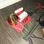
Maybe take a picture of your XO setup and its connections to the woofer and tweeter?
the circuit is a simple 1st order w an inductor and a notch, it's too easy, but i re-did it anyways.
Attachments
Last edited:
Amps with high output impedance will cause exactly pros and cons what we see here, are used amp high or low impedance Aatto 🙂
As X posted pages back to get measurements in agreement with Xsim simulation then ported SBA woofers double peak impedance needs in situation measurement for enclosure, REW can do this job and there is a how to guide looking in menu "Help" then "Impedance Measurements".
There is a 0,88 ohms DCR for that Jantzen inductor plus real world run of speaker cables, sum of these numbers can be filled into Xsim indutor or add another virtual resistor to count for these variances.
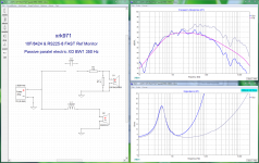
If it can help in a comparison find below a year 2015 simulation how X's speaker looked on design axis when Xsim is feeded both a frd and zma file for actual enclosure situation. With a lifted C1 component HF section is open circuit to plot only LF section, grey traces are raw woofer and filtered is blue traces plus there's a textbook target curve with BW2 76Hz high pass and two low passes where one is BW2 at 17kHz (stopband) and the other is BW1 at 800Hz (XO point).
As X posted pages back to get measurements in agreement with Xsim simulation then ported SBA woofers double peak impedance needs in situation measurement for enclosure, REW can do this job and there is a how to guide looking in menu "Help" then "Impedance Measurements".
There is a 0,88 ohms DCR for that Jantzen inductor plus real world run of speaker cables, sum of these numbers can be filled into Xsim indutor or add another virtual resistor to count for these variances.
If it can help in a comparison find below a year 2015 simulation how X's speaker looked on design axis when Xsim is feeded both a frd and zma file for actual enclosure situation. With a lifted C1 component HF section is open circuit to plot only LF section, grey traces are raw woofer and filtered is blue traces plus there's a textbook target curve with BW2 76Hz high pass and two low passes where one is BW2 at 17kHz (stopband) and the other is BW1 at 800Hz (XO point).
Attachments
thanks for the reply BYRTT, the amp is FH9 (low impedance).Amps with high output impedance will cause exactly pros and cons what we see here, are used amp high or low impedance Aatto 🙂
As X posted pages back to get measurements in agreement with Xsim simulation then ported SBA woofers double peak impedance needs in situation measurement for enclosure, REW can do this job and there is a how to guide looking in menu "Help" then "Impedance Measurements".
I will do the REW impedance measurement thing and we will see how it goes.
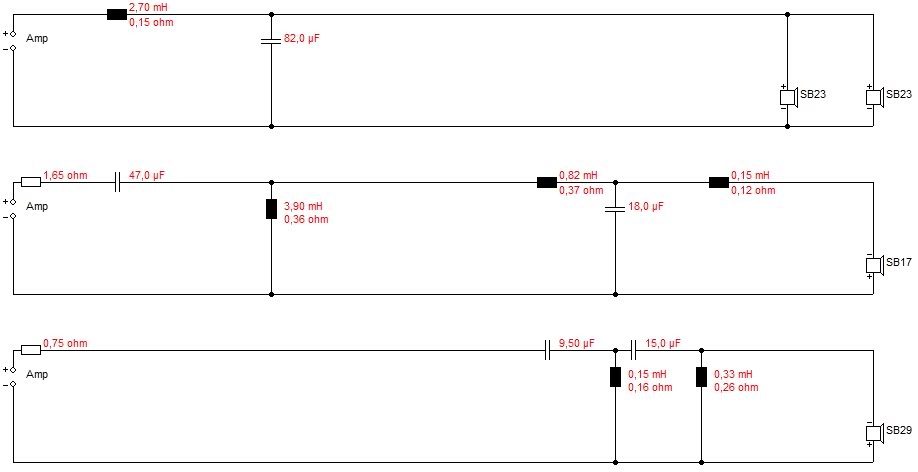
I saw this crossover from a member here in SB Acoustics 3 ways thread. he uses a 2nd order on SBA woofer with 2.5mH inductor (same as mine) and an 82uf cab in parallel with woofer, I simulated it and it causes some dip in total plot since this roll the woofer pretty steep but I do not trust xsim (or at least until i measured the impedance in cab) so I will try this maybe with a lower value cab and will report back.
Attachments
Last edited:
I tried to measure the impedance as described in REW but w no luck, it keeps giving me error, so i will try that again later 
I tried to measure the drivers again just to start from scratch, but came across some interesting results. I got totally different results this time, this is the FR slob from a few days ago:
this is today's measurement from the same spot...
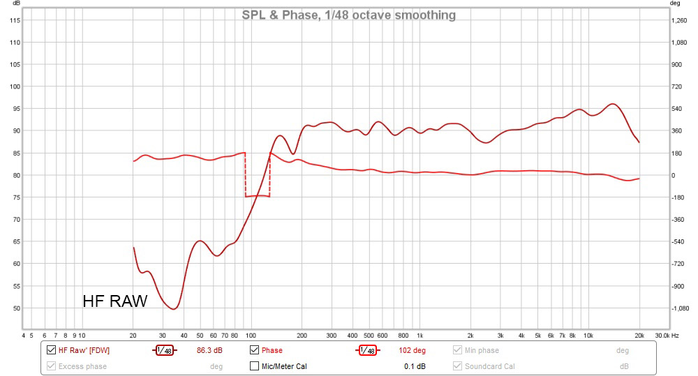
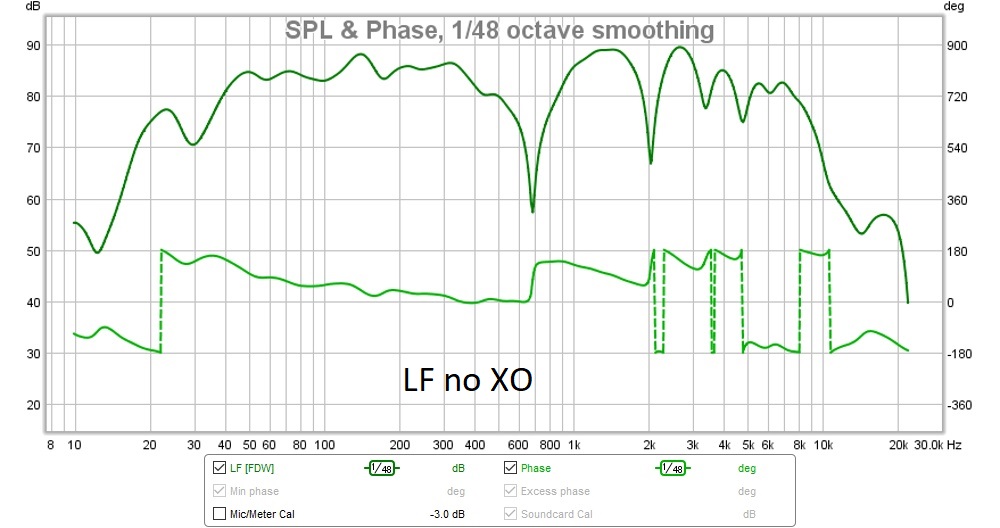
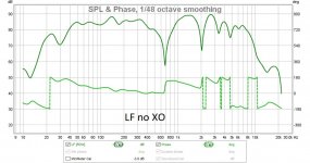
the woofer (today's measurement):
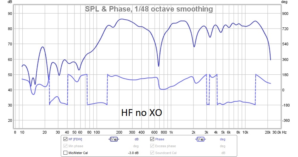
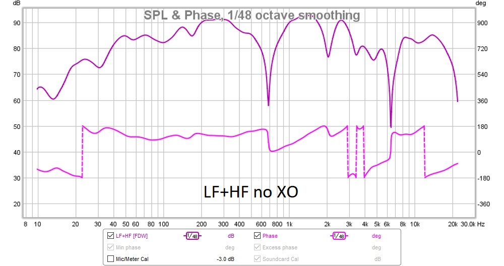
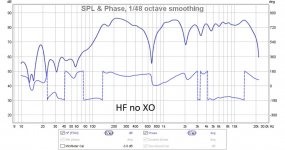
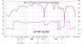
today's measurement woofer+FR no XO:
Woofer+FR no XO from a fews ago:
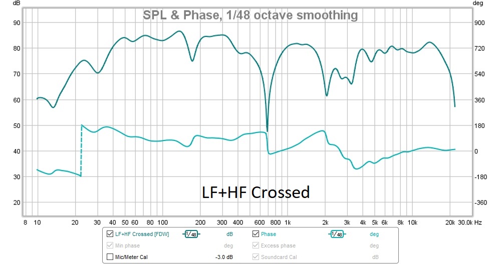
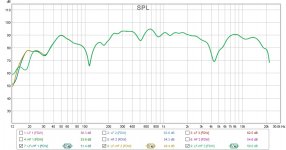
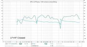
Woofer+FR with XO from today:
Woofer+FR with XO from a few days ago:
I tried to measure the drivers again just to start from scratch, but came across some interesting results. I got totally different results this time, this is the FR slob from a few days ago:
this is today's measurement from the same spot...
the woofer (today's measurement):
today's measurement woofer+FR no XO:
Woofer+FR no XO from a fews ago:
Woofer+FR with XO from today:
Woofer+FR with XO from a few days ago:
Attachments

Try elevating your driver at least 1m above the floor and set mic 0.5m away and use Frequency Dependent Window (FDW) with 6 cycles. This will eliminate effect of reflections which may be causing the dips. You will be seeing intrinsic response of driver on the baffle. Not floor bounce etc.
I guess i will have to do that, all these weird dips is probably reflections but i can't get my head around the first measurement. it looks totally different. i hope i m not doing some stupid mistakes here.
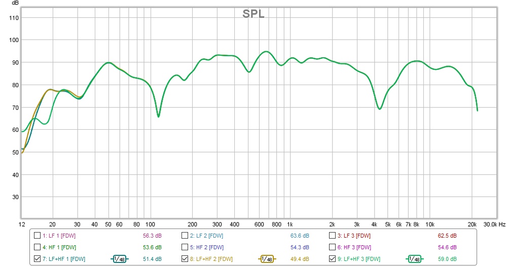
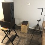
OK, it took me long enough to do but I finally got around to start measuring.
So I placed the speaker with at least a meter away from any walls and the Fullrange was about a meter and half above the floor, so not much reflection and definitely no comb reflections, Mic also placed about a meter away pointing at fullrange.
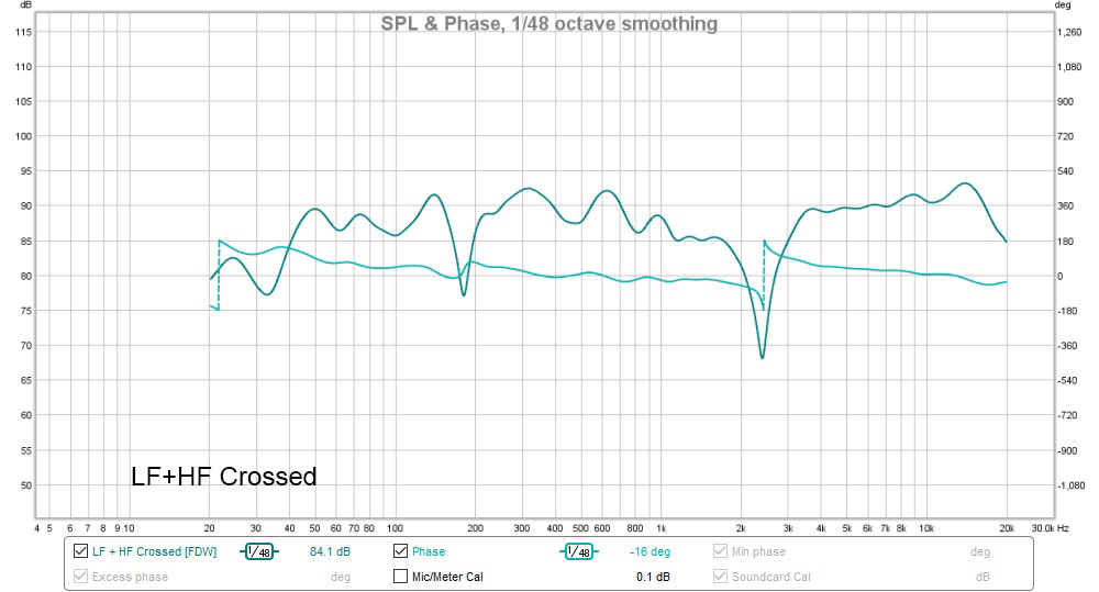
I got the same results, looks like the dip is caused by woofer interfering with the fullrange, and the crossover cannot roll the speakers off right. what can cause this ? no matter how I simulate this the crossover It should roll the drivers much steeper, in this case looks like the crossover acts more like padding than actually rolling off the drivers.
So I placed the speaker with at least a meter away from any walls and the Fullrange was about a meter and half above the floor, so not much reflection and definitely no comb reflections, Mic also placed about a meter away pointing at fullrange.
I got the same results, looks like the dip is caused by woofer interfering with the fullrange, and the crossover cannot roll the speakers off right. what can cause this ? no matter how I simulate this the crossover It should roll the drivers much steeper, in this case looks like the crossover acts more like padding than actually rolling off the drivers.
Attachments
-
 IMG_3301.jpg279 KB · Views: 493
 -
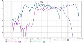 All Crossed.jpg127.3 KB · Views: 139
 -
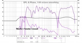 LF+HF Crossed.jpg115.4 KB · Views: 127
 -
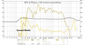
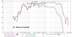 Woofer Raw vs Crossed.jpg107.8 KB · Views: 116
 -
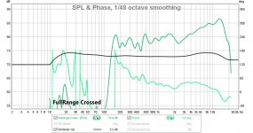
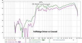 FullRange Raw vs Crossed.jpg112.6 KB · Views: 131
 -
 Woofer Crossed.jpg109.4 KB · Views: 462
 -
 FullRange Crossed.jpg108.1 KB · Views: 480
 -
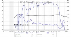 Woofer Driver in Cab.jpg111.7 KB · Views: 478
 -
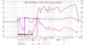 FullRange Driver in Cab.jpg117.5 KB · Views: 495
Can you double check your actual crossover wiring connections again? You must have a wiring error somewhere as the 10F should not fall off a steep cliff at 150Hz like that. I should have a gradual -6dB/octave rolloff from about 1kHz. It’s almost like there is an inadvertent cross connection somewhere.
Please post your crossover schematic again as measured above.
Thanks.
Please post your crossover schematic again as measured above.
Thanks.
Aatto's mic is too close to wall! The hop at 180Hz and dip below it is perhaps reflection from wall. Measurements below 300Hz are always very tricky to evaluate... Place the mic at the center of the room and the speaker diagonally at 60cm distance!
Nearfield is better to look at xo slope, but then we must estimate what baffle dimensions do for that. At 50-60cm distance usually the BS is showing well.
Nearfield is better to look at xo slope, but then we must estimate what baffle dimensions do for that. At 50-60cm distance usually the BS is showing well.
I agree that mic should be at 50cm to 60cm and with FDW 6 cycles will usually remove effects of room reflections.
I am mostly concerned that XO is miswired because the 10F with a 50uF cap usually starts rolling off below 900Hz.
I am mostly concerned that XO is miswired because the 10F with a 50uF cap usually starts rolling off below 900Hz.
Can you double check your actual crossover wiring connections again? You must have a wiring error somewhere as the 10F should not fall off a steep cliff at 150Hz like that. I should have a gradual -6dB/octave rolloff from about 1kHz. It’s almost like there is an inadvertent cross connection somewhere.
Please post your crossover schematic again as measured above.
Thanks.
Aatto's mic is too close to wall! The hop at 180Hz and dip below it is perhaps reflection from wall. Measurements below 300Hz are always very tricky to evaluate... Place the mic at the center of the room and the speaker diagonally at 60cm distance!
Nearfield is better to look at xo slope, but then we must estimate what baffle dimensions do for that. At 50-60cm distance usually the BS is showing well.
I agree that mic should be at 50cm to 60cm and with FDW 6 cycles will usually remove effects of room reflections.
I am mostly concerned that XO is miswired because the 10F with a 50uF cap usually starts rolling off below 900Hz.
Thanks for the inputs,
I will place the mic closer and will do the measurement again, and I did the 6 cycles FDW on posted slobs, I also did re-wire the cross over but this time i will take it apart and will do the measurements with each components.
attached is the crossover i m using.
Attachments

Try adding a R2 4.7R across the terminals of the 10F - just curious what it would look like if you tried my exact XO used for 10F and RS225
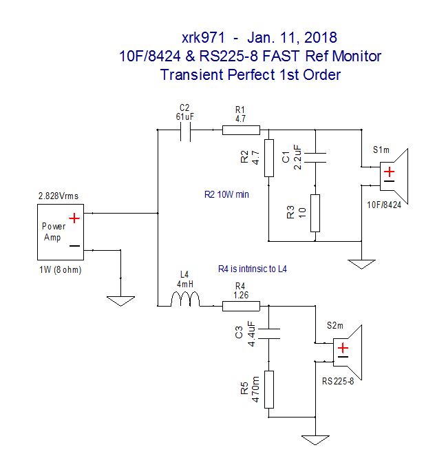
Also add Zobel R3 and C1.
Boost woofer coil to 4mH.
Also add Zobel R3 and C1.
Boost woofer coil to 4mH.
Last edited:
Try adding a R2 4.7R across the terminals of the 10F - just curious what it would look like if you tried my exact XO used for 10F and RS225
Also add Zobel R3 and C1.
Boost woofer coil to 4mH.
Thanks, I will add the R2 ( BYRTT suggested that too but to be honest I forgot )
will also add the Zobel as well since I already have the parts.
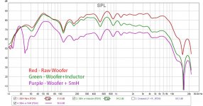
I did measure the woofer with a 5mH (2.5+2.5mh) instead if 2.5 and as you see it only acts like a padding resistor rather than rolling off the slob, I also did simulate the woofer in Xsim with a 0.25mH instead of 2.5mH and the results were similar to actual measurements with 2.5mH in my setup !, I m pretty sure the inductors are 2.5mH since they are way bigger than 0.25mH and also it is very unlikely that both of them are faulty, so I still cannot figure out what is going on, will do more measurements ( hopefully tomorrow ) and will report back.
Thanks
A.
Attachments

Last edited:
Do you have a DATS or other means to measure the mH of those inductors? Are they labeled as such from manufacturer? One other thing - are you sure you only have one speaker on/connected at a time during measurement? Ambient sound from second speaker can really mess things up if forget to disconnect.
- Home
- Loudspeakers
- Full Range
- 10F/8424 & RS225-8 FAST / WAW Ref Monitor