Test 1: Take the driver out, test it open baffle plus test it open baffle with cap...
Fix a temporary baffle to hold it...
Test 2: measure the impedance of the 10F in the enclosure, both with and without cap.
Fix a temporary baffle to hold it...
Test 2: measure the impedance of the 10F in the enclosure, both with and without cap.
Thanks for the replies,
The speaker actually does not sound as bad as it looks in Frequency Response, I thought I would notice such dip but maybe I m loosing my ear, but that makes me suspicious of my equipment or that I m doing something wrong, I have two audio interfaces (will use the other one this time), the mic is umik-1 and I did test both speakers separately.
The FR Driver has a dagger enclosure, it is sealed off but it is possible that it has air leak somewhere, I will look into this.
I will do the test outside the cabinet on an open baffle setup as wesayso suggested and will report back.
I m not sure if I get what you mean
The speaker actually does not sound as bad as it looks in Frequency Response, I thought I would notice such dip but maybe I m loosing my ear, but that makes me suspicious of my equipment or that I m doing something wrong, I have two audio interfaces (will use the other one this time), the mic is umik-1 and I did test both speakers separately.
The FR Driver has a dagger enclosure, it is sealed off but it is possible that it has air leak somewhere, I will look into this.
I will do the test outside the cabinet on an open baffle setup as wesayso suggested and will report back.
Chiming in late....perhaps it has already been suggested.
Try to hook up a fixed resistor (4 - 8 Ohms depending on your driver Z) instead of the drivers and look at the filter curves. With a pure resistive load, any component / wiring issues should come up clearly.
I m not sure if I get what you mean
Measuring FR, but not the acoustic, just the electric filter response, i.e. voltage over the load resistor. I suggested that because if it's not the driver or the enclosure, than must be something wrong with the filter (components). That's easily measured with a pure resistive load, and if the measurement corresponds with the expected filter FR's, you can exclude issues with the filter components, wiring, solder joints, whatever.[...]
I m not sure if I get what you mean
So basically jsut test the components making sure the problem is not from there, thanks got it 🙂Measuring FR, but not the acoustic, just the electric filter response, i.e. voltage over the load resistor. I suggested that because if it's not the driver or the enclosure, than must be something wrong with the filter (components). That's easily measured with a pure resistive load, and if the measurement corresponds with the expected filter FR's, you can exclude issues with the filter components, wiring, solder joints, whatever.
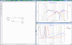
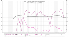
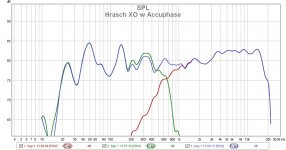
Theoretical into simulation it looks what is Aatto's real world case can be possible is the truth, in below XSim simulation traced amplitude responses from each published data sheet for SBA23NRX and 10F/8424 and did the math in REW (datasheet times bafflestep loss and difraction for Aatto's enclosure plus a 35Hz boost and 4th order roll off for woofer), then a homemade zma-file in a dual peak 35Hz one for woofer and used one of xrk971's real world DATS measurements for his 10F dagger combination. When acoustic center for woofer is about 1 inch too close to microphone relative to 10F we get below theoretical synthetic responses to compare with Aatto's latest real worl measurement ?
Attachments
Last edited:
Wow, thanks Byrtt. So it looks like the use of the RS225-8 is key to making the flat upside down woofer on top baffle work? Why does the 10F fall off so steeply at 150 MHz.
Theoretical into simulation it looks what is Aatto's real world case can be possible is the truth, in below XSim simulation traced amplitude responses from each published data sheet for SBA23NRX and 10F/8424 and did the math in REW (datasheet times bafflestep loss and difraction for Aatto's enclosure plus a 35Hz boost and 4th order roll off for woofer), then a homemade zma-file in a dual peak 35Hz one for woofer and used one of xrk971's real world DATS measurements for his 10F dagger combination. When acoustic center for woofer is about 1 inch too close to microphone relative to 10F we get below theoretical synthetic responses to compare with Aatto's latest real worl measurement ?
O WOW, that s is some calculations alright 🙂 I appreciate the time and effort you put into this, so i think we found the black sheep then, at least for the dip issue, it's back to DSP for me

Wow, thanks Byrtt. So it looks like the use of the RS225-8 is key to making the flat upside down woofer on top baffle work? Why does the 10F fall off so steeply at 150 MHz.
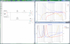
Yes its position in space of the two acoustic centers relative to microphone that is so sensible to create various interference patterns plus most woofers have a amplitude and phase havoc at breakup area because they expected used with steeper filters much lower, so the wide band covering using 1st order has a cost here when the two sources has physical spacing, in below graphs there is a 3 inch delay for 10F and worst interferense pattern looks go away. The steeply falloff at 150Hz is because when factory sheet is traced one only gets numbers for that amplitude curve into frd-file without any phase data and to repair that problem one can use "Derive" feature in XSim to get phase to follow amplitude and i probably set its HP filter at about 150Hz at that time even Aatto told his dagger was at 182Hz planning, but it should not be a big problem for stuff we here try to figure out.
Attachments
Last edited:
O WOW, that s is some calculations alright 🙂 I appreciate the time and effort you put into this, so i think we found the black sheep then, at least for the dip issue, it's back to DSP for me
Yes can imagine that was the black sheep and if you more real world curious you can probably test it measure at say 5-10 microphone heights and you will get different looking interference patterns for all of them except for one where acoustic center distance is same or lets say optimal for these simple use of few components for slopes 🙂
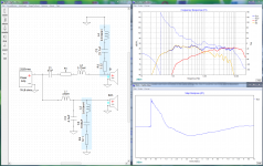
Ha ha back to DSP makes me smile a bit because 1st order is often the worst eater of expensive components because of the wide bandwidth coverage so DSP would not be bad here to get slopes alot smoother and even manipulated wider too, a few minuttes quick and dirty example is below how component numbers accelerates too fast when one try get smoother slopes for such wide coverage.
Attachments
Last edited:
Yes can imagine that was the black sheep and if you more real world curious you can probably test it measure at say 5-10 microphone heights and you will get different looking interference patterns for all of them except for one where acoustic center distance is same or lets say optimal for these simple use of few components for slopes 🙂
Ha ha back to DSP makes me smile a bit because 1st order is often the worst eater of expensive components because of the wide bandwidth coverage so DSP would not be bad here to get slopes alot smoother and even manipulated wider too, a few minuttes quick and dirty example is below how component numbers accelerates too fast when one try get smoother slopes for such wide coverage.
Yeah DSP looks like the way to go in my case 😀 at least for now.
I may give this circuit a try one day 😀 thanks again for detailed and well explained answers 🙂 cheers

hi, im very close to pulling the trigger on the passive version of this speaker. however the dayton woofer is hard to source in my country, where as Scanspeak 18W/8434, 18W/4434G00
and 22W/8534G00http://www.scan-speak.dk/datasheet/pdf/22w-8534g00.pdf
are readily available. im particularly interested in implementing 22w in your design. could you help me out in making the crossover work?
i will be putting the woofer into a TL tower, btw, since i dont have a wife 😛
and 22W/8534G00http://www.scan-speak.dk/datasheet/pdf/22w-8534g00.pdf
are readily available. im particularly interested in implementing 22w in your design. could you help me out in making the crossover work?
i will be putting the woofer into a TL tower, btw, since i dont have a wife 😛
Last edited by a moderator:
hi, im very close to pulling the trigger on the passive version of this speaker. however the dayton woofer is hard to source in my country, where as Scanspeak 18W/8434, 18W/4434G00
and 22W/8534G00http://www.scan-speak.dk/datasheet/pdf/22w-8534g00.pdf
are readily available. im particularly interested in implementing 22w in your design. could you help me out in making the crossover work?
i will be putting the woofer into a TL tower, btw, since i dont have a wife 😛
I think it could work with the 22W. The TS parameters are close with same Qts, fs, sensitivity, Bl, but Vas is 22W is almost double. You will need a larger cabinet or go vented in order to go deep.
If you can get me the FRD and ZMA file I can run the Xsim for you to get the optimal Xo. Use the graph trace digitizing program.
I simmed a MLTL with the TB W8-1722 ( that's the woofer, not the 1772 full range) and it looked amazing.
I haven't had the chance to build it yet.
I haven't had the chance to build it yet.
Question if i may please? Pulling the full range out of the dagger tl to free air/open baffle, wouldnt i lose some perceived bass due to rear wave cancellation?
Bass is from the Dayton woofer, not from the FR.
Since it is crossed at 500Hz, with a simple first order, that's where the perceived bass will come from. So, yes, you could mount the FR on OB.
Since it is crossed at 500Hz, with a simple first order, that's where the perceived bass will come from. So, yes, you could mount the FR on OB.
Bass is from the Dayton woofer, not from the FR.
Since it is crossed at 500Hz, with a simple first order, that's where the perceived bass will come from. So, yes, you could mount the FR on OB.
: ) Guess its not so simple or too relaxed way say woofer is where we get bass from, we probably used to that scheme in most systems is really 4th order acoustics and few is lower 2nd order acoustics, but this is only first order acoustics target so one decade below above suggested XO point we at 50Hz and mid-tweeter only depressed -20dB and even CD material can aproach a 20dB dynamic range : )
That said as long we inside with real walls room gain there will help in we can cut off some low end for the sake of 10Fs distortion down there but that cut off should also be done for woofer so its a global cut off for them both, relative to each other woofer and mid-tweeter needs to keep close to textbook slopes to have this filter work as intended, well one can use transient perfect speadsheet from J. Kreskovsky and sum filler driver slope with say woofer or mid-tweeter to get a closer to 2nd order slope for 10F but its a time consuming task sit and adjust speadsheets Fx and Gamma parameters to satisfying improvements after filler is summed with one or the other bandpass.
Can't stop thinking if folks are so relaxed about deviate from textbook slopes why don't they target a 2nd order slope from the start then because its probably where they end in reality being so relaxed about keeping a real 1st order acoustic rolloff.
Right, the roll off will appear more steep for the full range cuz the bass will just drop off.
Maybe put a bsc on the full range to combat this?
Or cross the woofer a tad bit higher so that theres a greater overlap?
Maybe put a bsc on the full range to combat this?
Or cross the woofer a tad bit higher so that theres a greater overlap?
I realize I was over simplistic, and in theory or measuring with a mic at 1m or less, and yes, we can see the 1st order on the 10F is affecting the woofer's output.
But, in reality, when sitting at a listening spot 3m away, just how much air will the small sealed 10F push towards the listener, compared to the much bigger woofer with a lot more Xmax?
Or have I got it wrong?
But, in reality, when sitting at a listening spot 3m away, just how much air will the small sealed 10F push towards the listener, compared to the much bigger woofer with a lot more Xmax?
Or have I got it wrong?
I used to own a statement monitor by jim holtz, and that had 4" tangband crossed at 350(?) To a dayton woofer. The tangband was mounted in an open back tunnel for a slight diapole effect and the amount of stuffing to it would affect the overall perceived bass. I even remember asking the designer about it and he said something about the tunnel providing sort of a bsc and to leave the 4" free air was to lose bass
- Home
- Loudspeakers
- Full Range
- 10F/8424 & RS225-8 FAST / WAW Ref Monitor