thanks for the replies guys,
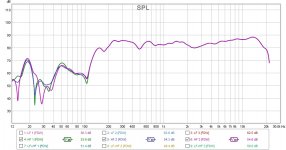
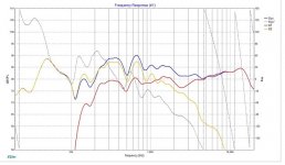
I followed the 1st order cross over simulated in xsim as in post #1187, crossed at 550Hz, followed by a notch on woofer and a pad on tweeter , and the plots doesn't look anything like what has been simulated, the cross over is way to simple to make any mistakes but i just finished printing two plates and will do the cross over again anyway.
the weird thing is such dips would be audible as it happened to me before and I use to hear dips and peaks while frequency sweeps but not here, the speaker sounds good i did another compare with my JBLs and even my headphones and still the speaker doesn't sound weird at all, so i measured it again this time i positioned the mic even closer about 1.5ft to eliminate any reflection and it s still the same and it s definitely the drivers as x said.
I ll try to work on this, any suggestions are welcome.
Hi Aatto,
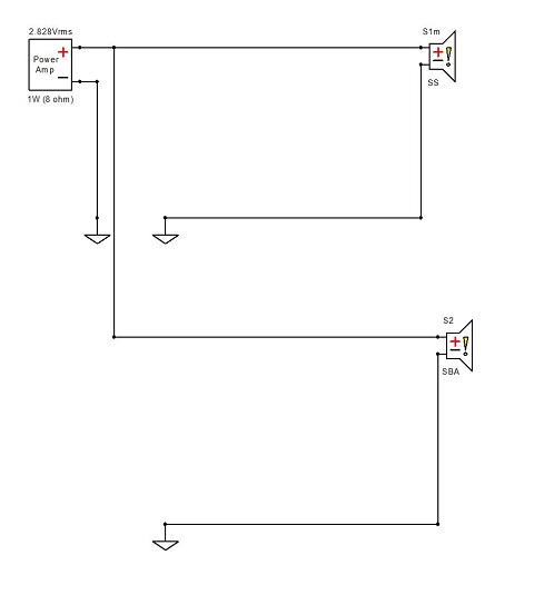
You can simulate the response based on actual measurements as you have a calibrated mic now. You need to measure 3 responses, each without touching the mic or speaker physically, but only changing wires. Measure the woofer by itself, then mid-tweet, then both in parallel (with two independent amp channels - not tied in parallel). All without XO electronics and full range 10Hz to 22kHz in REW. Then put the measured responses into either Xsim or PCD and your goal is to now adjust the axial delay of the tweeter until the resulting sim matches the combined curve *exactly* down to every little wiggle. Now you have determined by experiment the acoustic delay between the channels. Any additional delay you may need later to match phase will be on top of this.
Within this thread, a ways back are examples of my attempt to do this with the RS225 and 10F.
Its strange that you post such a steep curve that falls off at 100Hz for your 10F. If you high pass it with circa 50uF, it has to look different - a smooth -6dB/oct falloff starting circa 1000Hz and XO around 600Hz to 700Hz.
Same with the woofer, a 8ohm woofer with a circa 4mH coil will start falling off above 200Hz gradually and have circa -6dB/oct falloff with XO point circa 600Hz to 700Hz, maybe 1000Hz tops, not 2kHz.
You might want to take a look at some examples SATX did for me in terms of a sim with PCD. Although he was looking at a LR2 XO, the technique is the same.
10F/8424 & RS225-8 FAST Ref Monitor
Last edited:
Hi Aatto,
You can simulate the response based on actual measurements as you have a calibrated mic now. You need to measure 3 responses, each without touching the mic or speaker physically, but only changing wires. Measure the woofer by itself, then mid-tweet, then both in parallel (with two independent amp channels - not tied in parallel). All without XO electronics and full range 10Hz to 22kHz in REW. Then put the measured responses into either Xsim or PCD and your goal is to now adjust the axial delay of the tweeter until the resulting sim matches the combined curve *exactly* down to every little wiggle. Now you have determined by experiment the acoustic delay between the channels. Any additional delay you may need later to match phase will be on top of this.
Within this thread, a ways back are examples of my attempt to do this with the RS225 and 10F.
Its strange that you post such a steep curve that falls off at 100Hz for your 10F. If you high pass it with circa 50uF, it has to look different - a smooth -6dB/oct falloff starting circa 1000Hz and XO around 600Hz to 700Hz.
Same with the woofer, a 8ohm woofer with a circa 4mH coil will start falling off above 200Hz gradually and have circa -6dB/oct falloff with XO point circa 600Hz to 700Hz, maybe 1000Hz tops, not 2kHz.
You might want to take a look at some examples SATX did for me in terms of a sim with PCD. Although he was looking at a LR2 XO, the technique is the same.
10F/8424 & RS225-8 FAST Ref Monitor
Thanks X, i will start studying and will start measuring as you said.
This is indeed very weird, as you said it's like the electronics are not doing what they supposed to, which does not make any sense whatsoever.
i tried to find some XO for same drivers to have an idea of what a professional XO looks like for this and most of them are usually simple XOs.
Troels uses a first order on same woofer in his SBA 3 way.

Those look good, now load them into Xsim or PCD and see if you can generate the sum in the simulation. Once you have that - the electrical transformations via XO components will follow the sim almost exactly.
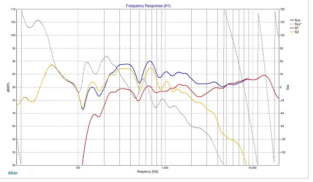
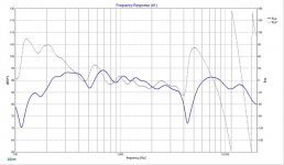
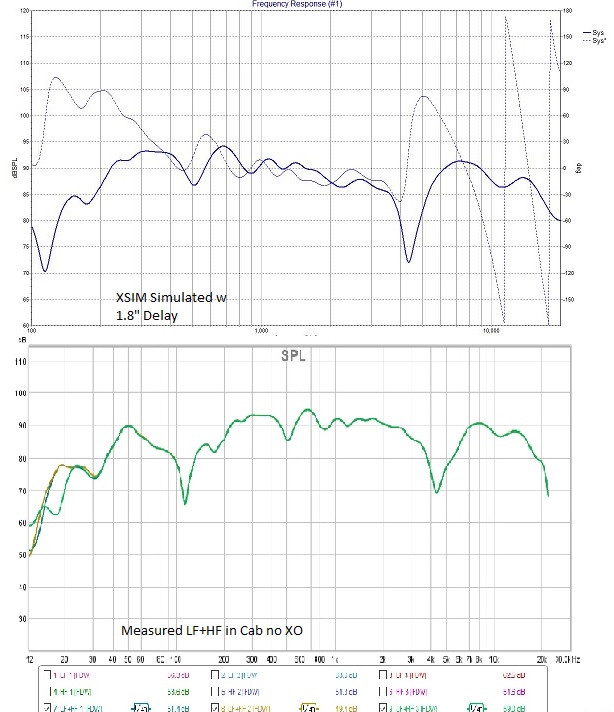
ok, this is weird, i m not sure if it's the xsim or I m doing something wrong here, loaded the files into xsim, and by adding a 1.8" delay to tweeter it matched the respond that i got from measuring.
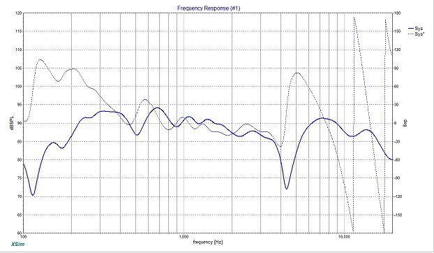
then without changing anything, i added the XO components and it rolls the woofer just right and the dip is gone. the weird part is it did roll the HF just like what i measured w XO.
then without changing anything, i added the XO components and it rolls the woofer just right and the dip is gone. the weird part is it did roll the HF just like what i measured w XO.
Attachments

Last edited:
That means that you have a 1.9in acoustical center offset in your drivers relative to he baffle and your XO was so out of Nand that they were both basicallntunning “fullrange” and had a natural XO at 2kHz.
Now see if the same delay gets you the sum of woofer + midtweeter.
Now see if the same delay gets you the sum of woofer + midtweeter.

Now see if the same delay gets you the sum of woofer + midtweeter.
oh ok, you mean the original drivers not the measured in the cab ones. got it.
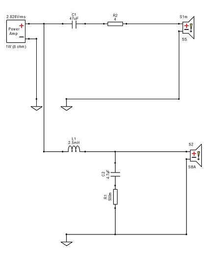
thanks for the tip, will add this in the sim as well.Using serial R2 alone adds overshoot where a L-Pad helps for that situation, suggest either add about 4,2 ohms as in below or go to "CircuitBlocks" menu and add a adjustable L-Pad should help a bit on overshoot.
I meant that the measurement should still be in the same cabinet/baffle - just no XO. Xsim needs to be able to replicate the two drivers (played together or SUM signal on mic) in the cabinet without a XO correctly before trying to model it with a crossover.
I get what you mean, or at least i think i do ! don want to hijack your thread and make it about my problem. so i will try not to, and also maybe this will help someone later on.
so we need to simulate what is actually happening in the cab into sim, so i added separately measured (in the cab) HF and LF drivers into xsim, and with added 1.8" delay to HF the simulated slob matched the measured result of LF+HF in the cab (no XO at this point).
this is what you mean right ? so from this point I can start a crossover around this.
Attachments
Hi Aatto,
You are not hijacking at all - it's on topic as you are trying similar alignment and same mid-tweet and different woofer which I want to try as well (I bought a pair already but have not had chance to test or measure yet). Byrtt warned me about a mild dip in response around 200Hz I think. Its got deeper bass power than RS225, but that RS225 is a very smooth performer.
Please carry on!
Cheers,
X
Alright thanks X,
so I did as i stated, i matched the Xsim to real measured HF+LF in the cab with no XO.
Now if i add the inductor to the woofer, it will roll off nicely and the 2-3k dip is gone in Xsim. but this does not happen in real world, if i add the inductor to my woofer it does not roll it off as simulated and i will still have the dip.
That might mean that you do not have the correct impedance curve. Did you measure the impedance sweep with say, a DATS? Are you using a digitized factory impedance curve?
Are you using correct 8ohm vs 4ohm curves? Something seems really off. The response through an inductor has to fall off as frequency goes up. Try 4mH in real life and see if that helps.
at work and take every free sec i have to work on this !
any how i managed to retrace both drivers, both FRD & ZMA.
So the files that i had and used in my Xsim, I got'm both from a member here and look like the SPL graphs were alright but the impedance was off ! I get different behavior with new traced files, but even with new ZMA combined with my measured in cab woofer FRD, as soon as I add the inductor it will roll the woofer off and the dip disappears, I will try to work some more on this, will report back.
Perhaps you have a bad or incorrectly labeled inductor? Do you have a part number or photo? Maybe it is a 0.2mH inductor not 2mH?
Perhaps you have a bad or incorrectly labeled inductor? Do you have a part number or photo? Maybe it is a 0.2mH inductor not 2mH?
na, that's not the case, it is Parts-express Jantzen inductor, it is the same as the picture and it is too big to be 0.2.
I will do more measuring hopefully tonight.
Edit, I simulated the woofer with 0.2mH and it matches the roll off i get !!!
Last edited:
- Home
- Loudspeakers
- Full Range
- 10F/8424 & RS225-8 FAST / WAW Ref Monitor