I am going to start cutting the BB plywood tomorrow. Is there any reason to install a removable back ?.
I am thinking that if one applies the foam or whatever sound insulation they are using, is there really a need for a removable back panel.
Thanks
I am thinking that if one applies the foam or whatever sound insulation they are using, is there really a need for a removable back panel.
Thanks
No need for removable back. It is just more chance for an air leak. There is plenty of room to access the front chamber through the woofer cutout to install the crossover board. Just make sure you install the eggcrate foam before sealing up the sides.
Builders,
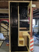
Had some of my buds help me rip the 4x8 sheets of BB ply. Just have to trim to size. Couple of general questions about the build. I call this a mini build guide:
1. Are any screws used for attaching sides, bottoms, tops etc.., or is it all the glue of choice and clamping ?
2. I assume that one would start with a side panel and glue in the internal TL line pieces ?
3. Glue and clamp the bottom section of front baffle, the bottom of the enclosure, and the back as one complete step ?
4. Glue and clamp, the top piece, the front baffle (already cut out for drivers ) as one complete step ?
5. Install drivers, sports cone, etc..., and stuffing of choice ?
6. Figure out X over location and install accordingly ?
7. As a test run, clamp the remaining side of the enclosure and do a sound test. Adjust accordingly for taste and then glue the final side in place ?
8. Figure out finish to apply ?
Thanks
Hi Myles,
You have it right. No screws needed unless removable panel. But doesn’t hurt to use screws and glue. There are several builds in this thread where the steps are shown in progress photographs. But glueing the internal channels and outer walls on one side first and then clamping final second side after installing internal damping foam/felt is the way to go. The XO can be installed in main cavity behind woofer or on divider wall after speaker is built. Make sure you run wires to binding posts from back to front before glueing.
You have it right. No screws needed unless removable panel. But doesn’t hurt to use screws and glue. There are several builds in this thread where the steps are shown in progress photographs. But glueing the internal channels and outer walls on one side first and then clamping final second side after installing internal damping foam/felt is the way to go. The XO can be installed in main cavity behind woofer or on divider wall after speaker is built. Make sure you run wires to binding posts from back to front before glueing.
Thanks X,
On the 90 degree joints, I will be using a few of these handy devices that are used in furniture and cabinet making. Need to order some sport cones soon. Looking forward to this build.

MM
On the 90 degree joints, I will be using a few of these handy devices that are used in furniture and cabinet making. Need to order some sport cones soon. Looking forward to this build.
MM
X what element of the XO gives us the BSC.?
I assumed it was the inherent R of L4 but in XSim when I lower the R it raises the LF, so to boost the LF as BSC does(?) I would have expected a lower DCR coil to be used?
I'm just trying to understand the implementation of the BSC!
I assumed it was the inherent R of L4 but in XSim when I lower the R it raises the LF, so to boost the LF as BSC does(?) I would have expected a lower DCR coil to be used?
I'm just trying to understand the implementation of the BSC!
The baffle step occurs around the same region as the XO - circa 800Hz. So the natural falloff from the low pass filter achieves this. The full range driver (nominally 87dB) is then attenuated with R1/R2 to match the bass level that has now fallen off to 82.4dB.


nikpolini those look to be coming along nicely!
Thanks again for this thread and plans xrk971
It has been many decades since I had speakers worth listening too....
Still have not tried them with anything but a standard Sony amp.
They sound great but I know there is more to be had.
Could try an F5 but its a bit small
my other good sounding amp is way too big, bridged/balanced 400W/8R.
Plan is to split that one into two 100W stereo amps
Got some PExpress buyout planer tweeters and crossed them 2nd order at 10khz.
Placed on top 3" back from front.using 20R serial attenuation so as to add just a bit.
you see I like the sound of Stax headphones or planer magnetic's for certain sounds like cymbals and the metallic
sound that a drum kit makes when it resonates
Thought about mounting them next to the fullrange BUT that is permanent and I don't know if that would work
and not mess up the good I have now..... Too much speaker science required.......
Super work, Nikpolini! Looking very nice.
@Congo5 - I have tried a similar thing as well with AMTs and they do add sparkle and air. The super tweeter on top 3in back is the way to go. If you add them to the front baffle, it will require real measurements and a 3 way crossover.
@Congo5 - I have tried a similar thing as well with AMTs and they do add sparkle and air. The super tweeter on top 3in back is the way to go. If you add them to the front baffle, it will require real measurements and a 3 way crossover.
Hello all..
Now I want to try the bookshelf version and having an untested newly built CNC......
So foam first then Baltic Birch after I get the cad/cam and machine dialed in.
Used xrk's numbers +0.250 in one direction because I used different bracing.
just guessing how much volume I used up.


Now I want to try the bookshelf version and having an untested newly built CNC......
So foam first then Baltic Birch after I get the cad/cam and machine dialed in.
Used xrk's numbers +0.250 in one direction because I used different bracing.
just guessing how much volume I used up.
anyway thanks,internal dimensions I settled on were 8in wide x 12in deep x 16in tall
Very interesting. Would you apply the short waveguide only to the 3.3 mid-high (Visaton B80) or even to the Dayton RS225-8? Finally, regarding the curved shape, are you aware of a calculator that can provide us with the curvatures and the internal volume?A while ago member fluid ran sims for a driver in a flat baffle and the same driver with a rounded enclosure:
The relatively flat baffle:
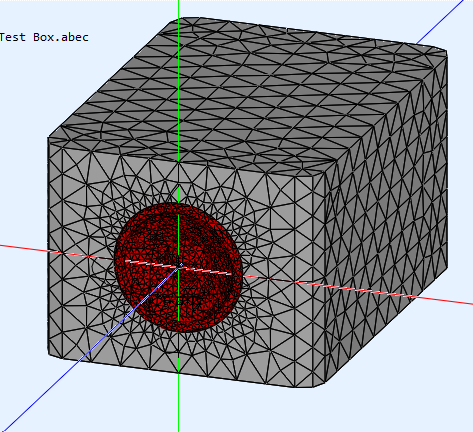
Versus the rounded enclosure:
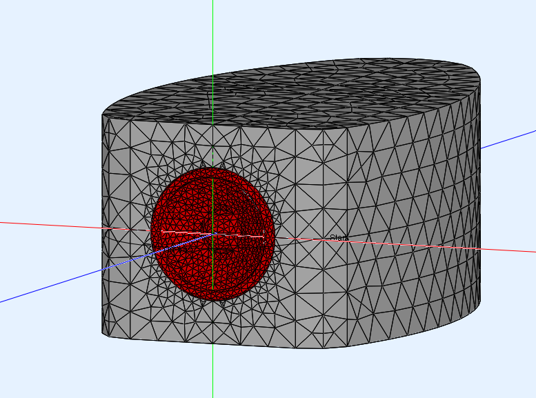
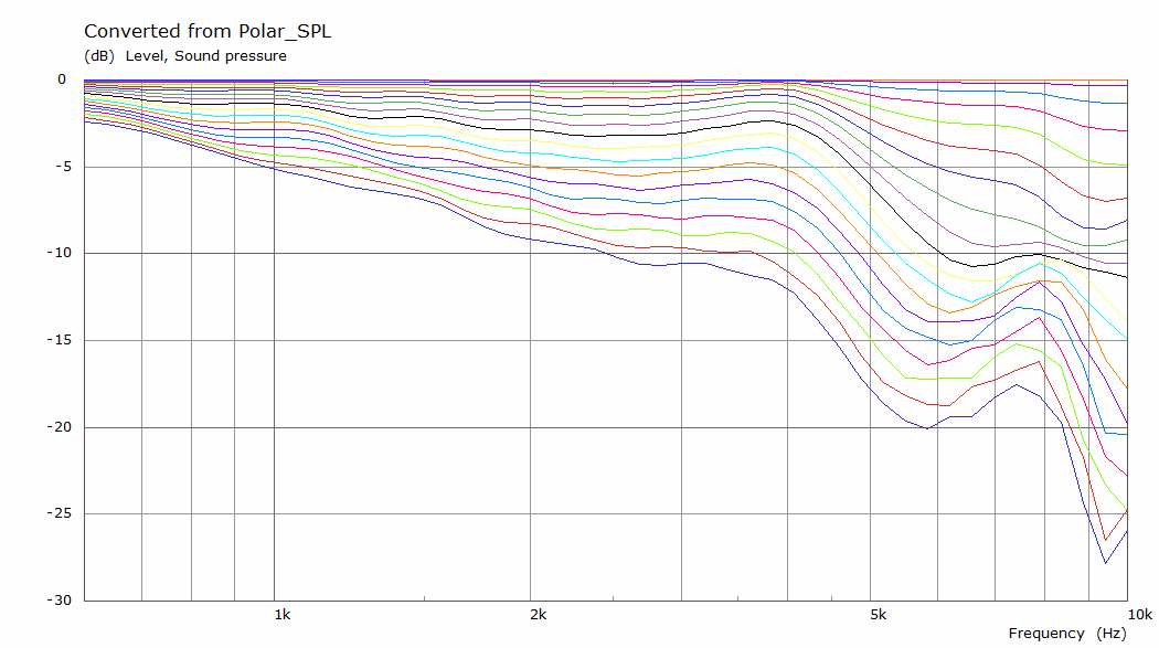
I'd say it is easy to spot differences. The first round-over used on that enclosure shape is only 25.5mm or about 1" radius. Yet the effect it has is quite obvious.
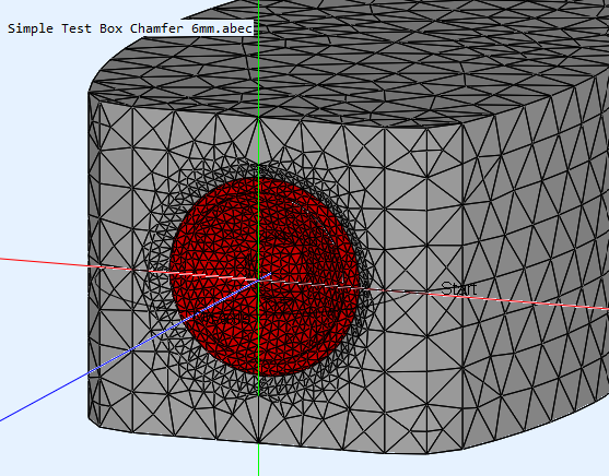
Taking this concept a step further, with the driver set back in the baffle with a small chamfer in front of the driver:
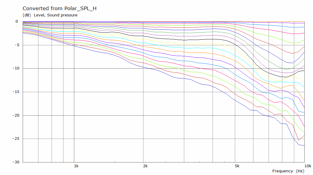
I'd say it's well worth it to try or play with things like that. Even if it means it needs a crossover adjustment to work it all out. 🙂
ABEC (Akabak 3D) is one such program. There is a thread on how to use it in the SW forum.
But just adding large radius chamfers is usually enough. Circa 1-2in radius. Avoid sharp edges or sharp lip structures.
But just adding large radius chamfers is usually enough. Circa 1-2in radius. Avoid sharp edges or sharp lip structures.
Many many thanks xrk, you are truly a great resource for many of us.ABEC (Akabak 3D) is one such program. There is a thread on how to use it in the SW forum.
But just adding large radius chamfers is usually enough. Circa 1-2in radius. Avoid sharp edges or sharp lip structures.
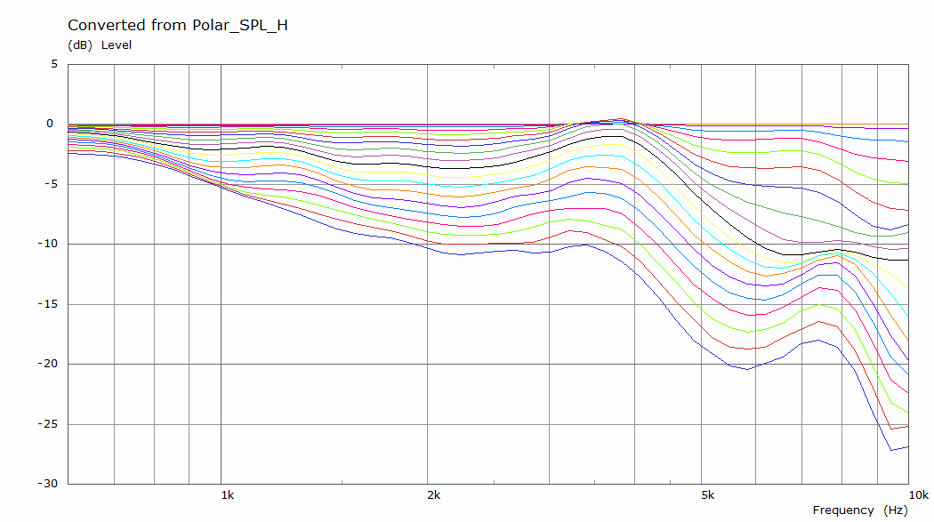
I'd say this waveguide is useful for the ~3.5" drivers as they play from midrange and up. Primarily function is to avoid diffraction as much as possible.
Which pays off in the off-axis results, which form an important part of what we hear from our room according to the Harman school of thought.
ABEC can calculate results, in my case intuition (and pure luck) led to the choices I made, somewhat helped by seeing prior measurements that had a filet in front of a back-mounted driver. I looked at the shape from a birds eye perspective to create the smoothest extension I could think off, starting with the cone of the driver (no sharp edges):

(the roll-surround forming the largest discontinuity)
But it didn't stop me from using a similar construction on my subwoofers 😉.

That was done purely for matching looks...

Avoiding diffraction never is a bad thing though, I'd certainly recommend it if you can within an audio project.
Which pays off in the off-axis results, which form an important part of what we hear from our room according to the Harman school of thought.
ABEC can calculate results, in my case intuition (and pure luck) led to the choices I made, somewhat helped by seeing prior measurements that had a filet in front of a back-mounted driver. I looked at the shape from a birds eye perspective to create the smoothest extension I could think off, starting with the cone of the driver (no sharp edges):
(the roll-surround forming the largest discontinuity)
But it didn't stop me from using a similar construction on my subwoofers 😉.
That was done purely for matching looks...
Avoiding diffraction never is a bad thing though, I'd certainly recommend it if you can within an audio project.
Last edited:
- Home
- Loudspeakers
- Full Range
- 10F/8424 & RS225-8 FAST / WAW Ref Monitor