The first way. I have never verified if you can do a cascaded 3-way Harsch XO. In theory it sounds like it could work. I think may have tried to do it once but it got complicated. I suppose the delay of the mid and tweeter both need to slide in unison to accommodate the woofer delay.
Thanks again, much appreciated. I have a nanodigi / Khadas tone board setup I use on my Mackie HR824 (8” Viva poly woofer and 1” metal dome in wave guide) to do room eq, but I have a third speaker for spares so may just bypassing the amp plate and use my Rotel rmb1066 to power and play around with different crossovers to get some experience.
I recently had a conversation off the board with xrk971. It was supposed to be a quick question, but it got... complicated. He asked me to take the posts and put them on the board so that others could learn as well... Here's what I have:
-----
I asked about the thread in general (all 2500+ posts of it) and he provided the following links for finding critical information:
He replied: (summarized)
The first post (which also serves as an index) :
10F/8424 & RS225-8 FAST / WAW Ref Monitor
Specifically, go here for the TL: (post 1961) - note this is with 1/2" ply interior
10F/8424 & RS225-8 FAST / WAW Ref Monitor
In a different thread (crossover board group buy), the plan for the all 3/4" ply TL can be found (post 90)
https://www.diyaudio.com/forums/gro...fast-waw-speaker-xo-pcb-gb-9.html#post6129100
Here is the XO for the 4 ohm woofer - RS225-4: (post 1019)
https://www.diyaudio.com/forums/ful...25-8-fast-waw-ref-monitor-95.html#post5305534
Here is the XO for the 8 ohm woofer - RS225-8: (Post 945)
10F/8424 & RS225-8 FAST / WAW Ref Monitor
-----
I then asked about something I read about a notch filter mentioned in one of the crossover posts, about alternate speakers (as the full range speaker specified was a bit rich for my wallet) and where one usually mounts the crossover.
He replied:
No notch to worry about - the listening height is the woofer axis not the 10F.
Almost any 2.5in to 3.5in 8ohm full range driver can be used. Adjust the resistor to match sensitivity. Examples that work well: TC9FD, TG9FD, 3FE25, 3FE22, RS100-8, PS95-8, B80, FR58EX, FR88EX, Tang Band W3-xxxx, Peerless 83xxxx 3.5in full range, etc. the star is the woofer RS225-8. You must use that woofer with the crossover.
I make front baffle removable so crossover is accessible. On TL I mount on removable back wall. Use the schematic from &/‘ 11, 2008 for the XO. It has the notch already.
-----
I then asked about interference between the drivers and where the interference line (not sure of the proper term) due to listening height difference between the ears and the speakers, and about tuning the crossover network for the other speakers.
He replied:
You won’t notice the bulk at the usual listening distances of 2m or more away from speaker. Being a transient perfect but non coaxial design, try to have the ear at about the woofer axis. Whether you tilt the speaker or change your seat height is ok. However, at usual listening distances of 2m or more, it doesn’t matter as much as the 3in time of flight difference between the woofer and fullrange becomes less and less important the farther you are away. Don’t worry about in other words. It will sound great. I am sitting 7 ft away and 15in above woofer axis and it still sounds great.
For any other full range, if 8ohms just adjust the two resistors R1 and R2 to balance the level. The design is nominally for 87dB at 2.83v ScanSpeak 10F. It’s a 4.7R/4.7R divider. For less sensitive 85dB driver use 2.2R/6.8R for R1/R2 - and adjust R1 in 0.5ohm increments by adding series or parallel resistance until it sounds good to you. For 82dB sensitive driver like SB65WBAC25-4 then use straight wire for R1 and leave off R2 for max sensitivity to match woofer (82.4dB at 2.83v after baffle step loss). Baffle step loss is the loss of bass SPL below the baffle step frequency (determined by width of baffle) and about 900Hz for this speaker. A wall mounted speaker has infinite baffle so no loss (they have 6dB more bass than free standing speaker).
-----
I then asked for some additional clarification about some of the term she had used (transient perfect, etc) and about a more specific recommendation for the smaller speaker.
He replied:
Try the Visaton B80 for $52 from Parts Express. It is my second choice. Sound 95% of the $105 ScanSpeak at half the price.
If you are an inch from back wall, that helps the bass a lot. You may need less attenuation on the full range. Beware of floor bounce cancellation or desk bounce cancellation if they are too close to the ground or sit at the back of a large table and you are on the edge like desktop monitors. This is where the reflected sound from the woofer cancels itself with the main air path causing a dip around 120Hz to 170Hz. The way to avoid is put speakers on a stand mount and away from floor or flat table.
Transient perfect is the sound from both drivers arriving at your ears aligned in time, in phase and in absolute magnitude. Percussion and dynamics are exceptionally realistic. Most multiway speakers are not transient perfect because they use higher order Linkwitz Riley crossovers that require the tweeter to be reverse polarity, and the they are not time aligned.
-----
There was a further discussion of the issues that could arise from placing the 40" tall TL speaker box on top of a 24" table (as we have no available floor space on that wall), and the possibility of reversing the speaker placement. He offered to see what the simulator thought of the reversal of the cones, and he hopes to do it when he gets some free time.
I also asked if a slight change in the bottom/front portion of the cabinet (moving the front wall forward 1/4", with the 'hole' being moved forward 1/4" to match) would cause any issues (to put a grill over the drivers), and I expressed concern that a reversal of the speakers would leave the cone behind the full range unsupported.
He replied:
Your small adjustments to the size to accommodate the grill are fine. The sports cone is pretty lightweight and if screwed and bonded with construction adhesive to the baffle, won’t need a support. That support was really a through hole to allow it to fit in the narrow space.
The height may not make much of a difference at 6ft (listening distance) - but the core design feature of this speaker is “transient perfect” meaning the sound from the woofer should reach the earnest (listener?) the same time as sound from the full range. And to do that requires the full range to be offset either through a stepped baffle or through geometry of placement. If you left it as designed, it could work well when floor standing by itself later.
I would appreciate it if you could go through the last (5-7 posts between us) and copy and paste into the thread. I am just too busy to do it.
Give me a few days to run the sim for you.
Thanks,
X
-----
Now everyone is caught up. 🙂
-----
I asked about the thread in general (all 2500+ posts of it) and he provided the following links for finding critical information:
He replied: (summarized)
The first post (which also serves as an index) :
10F/8424 & RS225-8 FAST / WAW Ref Monitor
Specifically, go here for the TL: (post 1961) - note this is with 1/2" ply interior
10F/8424 & RS225-8 FAST / WAW Ref Monitor
In a different thread (crossover board group buy), the plan for the all 3/4" ply TL can be found (post 90)
https://www.diyaudio.com/forums/gro...fast-waw-speaker-xo-pcb-gb-9.html#post6129100
Here is the XO for the 4 ohm woofer - RS225-4: (post 1019)
https://www.diyaudio.com/forums/ful...25-8-fast-waw-ref-monitor-95.html#post5305534
Here is the XO for the 8 ohm woofer - RS225-8: (Post 945)
10F/8424 & RS225-8 FAST / WAW Ref Monitor
-----
I then asked about something I read about a notch filter mentioned in one of the crossover posts, about alternate speakers (as the full range speaker specified was a bit rich for my wallet) and where one usually mounts the crossover.
He replied:
No notch to worry about - the listening height is the woofer axis not the 10F.
Almost any 2.5in to 3.5in 8ohm full range driver can be used. Adjust the resistor to match sensitivity. Examples that work well: TC9FD, TG9FD, 3FE25, 3FE22, RS100-8, PS95-8, B80, FR58EX, FR88EX, Tang Band W3-xxxx, Peerless 83xxxx 3.5in full range, etc. the star is the woofer RS225-8. You must use that woofer with the crossover.
I make front baffle removable so crossover is accessible. On TL I mount on removable back wall. Use the schematic from &/‘ 11, 2008 for the XO. It has the notch already.
-----
I then asked about interference between the drivers and where the interference line (not sure of the proper term) due to listening height difference between the ears and the speakers, and about tuning the crossover network for the other speakers.
He replied:
You won’t notice the bulk at the usual listening distances of 2m or more away from speaker. Being a transient perfect but non coaxial design, try to have the ear at about the woofer axis. Whether you tilt the speaker or change your seat height is ok. However, at usual listening distances of 2m or more, it doesn’t matter as much as the 3in time of flight difference between the woofer and fullrange becomes less and less important the farther you are away. Don’t worry about in other words. It will sound great. I am sitting 7 ft away and 15in above woofer axis and it still sounds great.
For any other full range, if 8ohms just adjust the two resistors R1 and R2 to balance the level. The design is nominally for 87dB at 2.83v ScanSpeak 10F. It’s a 4.7R/4.7R divider. For less sensitive 85dB driver use 2.2R/6.8R for R1/R2 - and adjust R1 in 0.5ohm increments by adding series or parallel resistance until it sounds good to you. For 82dB sensitive driver like SB65WBAC25-4 then use straight wire for R1 and leave off R2 for max sensitivity to match woofer (82.4dB at 2.83v after baffle step loss). Baffle step loss is the loss of bass SPL below the baffle step frequency (determined by width of baffle) and about 900Hz for this speaker. A wall mounted speaker has infinite baffle so no loss (they have 6dB more bass than free standing speaker).
-----
I then asked for some additional clarification about some of the term she had used (transient perfect, etc) and about a more specific recommendation for the smaller speaker.
He replied:
Try the Visaton B80 for $52 from Parts Express. It is my second choice. Sound 95% of the $105 ScanSpeak at half the price.
If you are an inch from back wall, that helps the bass a lot. You may need less attenuation on the full range. Beware of floor bounce cancellation or desk bounce cancellation if they are too close to the ground or sit at the back of a large table and you are on the edge like desktop monitors. This is where the reflected sound from the woofer cancels itself with the main air path causing a dip around 120Hz to 170Hz. The way to avoid is put speakers on a stand mount and away from floor or flat table.
Transient perfect is the sound from both drivers arriving at your ears aligned in time, in phase and in absolute magnitude. Percussion and dynamics are exceptionally realistic. Most multiway speakers are not transient perfect because they use higher order Linkwitz Riley crossovers that require the tweeter to be reverse polarity, and the they are not time aligned.
-----
There was a further discussion of the issues that could arise from placing the 40" tall TL speaker box on top of a 24" table (as we have no available floor space on that wall), and the possibility of reversing the speaker placement. He offered to see what the simulator thought of the reversal of the cones, and he hopes to do it when he gets some free time.
I also asked if a slight change in the bottom/front portion of the cabinet (moving the front wall forward 1/4", with the 'hole' being moved forward 1/4" to match) would cause any issues (to put a grill over the drivers), and I expressed concern that a reversal of the speakers would leave the cone behind the full range unsupported.
He replied:
Your small adjustments to the size to accommodate the grill are fine. The sports cone is pretty lightweight and if screwed and bonded with construction adhesive to the baffle, won’t need a support. That support was really a through hole to allow it to fit in the narrow space.
The height may not make much of a difference at 6ft (listening distance) - but the core design feature of this speaker is “transient perfect” meaning the sound from the woofer should reach the earnest (listener?) the same time as sound from the full range. And to do that requires the full range to be offset either through a stepped baffle or through geometry of placement. If you left it as designed, it could work well when floor standing by itself later.
I would appreciate it if you could go through the last (5-7 posts between us) and copy and paste into the thread. I am just too busy to do it.
Give me a few days to run the sim for you.
Thanks,
X
-----
Now everyone is caught up. 🙂
In reviewing all that information, I do have an additional question that might change things a little, and that is the possibility of turning the entirety of the TL box upside-down, placing the speaker-half of the box on the bottom. With a floor-standing speaker, having the drivers that close to the floor would cause problems, but mine will be sitting on a 24" table (at the front edge of it, as the tables are only 18" deep).
Note: in reversing the drivers, I simply put them in the other's position. With the smaller driver closest to the top, it could be moved much closer to the top edge, as there is plenty of room. I have no idea what that does to the balance of the sound for the larger speaker, though. Perhaps xrk971, after running the sim with the speaker positions reversed, can fill us in on the best placement for the inverted pair.
Code:
Distance above floor:          large spkr  small spkr
speakers in normal positions       34"       26.5"      * on floor
speakers in normal positions       58"       50.5"      * on 24" table
speakers positions reversed        50.5"     58"        * on 24" table
speakers in normal positions       30"       37.5"      * on 24" table, box upside-down
speakers positions reversed        37.5"     30"        * on 24" table, box upside-down
Note: in reversing the drivers, I simply put them in the other's position. With the smaller driver closest to the top, it could be moved much closer to the top edge, as there is plenty of room. I have no idea what that does to the balance of the sound for the larger speaker, though. Perhaps xrk971, after running the sim with the speaker positions reversed, can fill us in on the best placement for the inverted pair.
Ooops, make that two things:
How does one "tune" a crossover for a full-range that has a different sensitivity?
In my mind, the obvious thing to do is listed below, but I have no idea how safe it is to do, or if having one speaker out of the circuit will impact the way the XO behaves...
The steps to I would take:
- disconnect smaller speaker (so we get a measurement from the woofer)
- play a sine wave at XO freq
- measure SPL (this becomes our target SPL for the full-range driver)
- turn sound off ( 🙂 )
- reconnect smaller speaker
- disconnect the larger speaker
- play sine wave at XO freq
- measure SPL
- tune resistors until SPL matches the woofer
Does that make sense?
Is there a reason not to do it that way?
Is there a better way?
Is this way safe?
Simply change the attenuation resistor R1 up or down (to taste) until sound is balanced in bass and treble. It will sound either too bright and not enough bass, or too much bass and no sparkle. Values range from 0R to 10R. Go in 2 ohm or 1 ohm increments. You can also measure with a mic and REW software.
So I discovered that my TL had a bad seal in the back panel when I could feel small jets of air shooting out when playing some hip hop music real loud (circa 50wrms). This video shows conclusively using a candle you can detect air leaks. It turns out that the gasket used was a rather thin and firm white rubber and not the vinyl foam window weatherstrip stuff. I replaced the gasket with proper weatherstripping and the leak went away. Remeasured the impedance sweep and both speakers look like the right curve. The asymmetry went away and the impedance minimum is at the same 27Hz box frequency. What I thought was the anomaly on the right speaker also showed up now on the left speaker with the leak gone.
Both left and right now basically looks like the green curve:
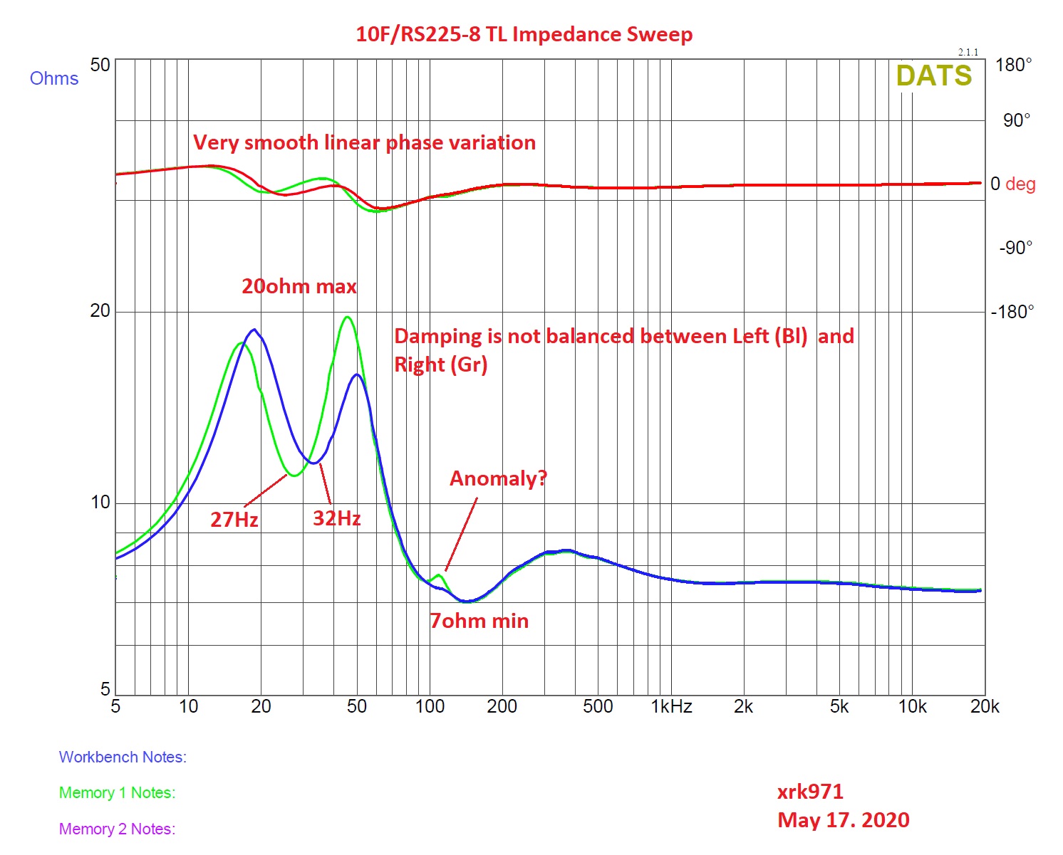
So, large amounts of asymmetry in the two impedance peaks is an indication of an air leak.
Both left and right now basically looks like the green curve:
So, large amounts of asymmetry in the two impedance peaks is an indication of an air leak.
Oh no, he's been thinking again!
I've been reading the thread and have a few more questions...
In post 1963
You mentioned that there might be a slightly shorter version of the TL that could sound as good or perhaps go a little lower.
- Did that ever pan out, or did it get set on the back burner for now?
- Might that help me with the "speaker too tall" issue? (or is "shorter" related to length of the TL, not speaker?)
- No pressure, but did you get a chance to run the sim with the speakers reversed?
My concern with the inversion of the speakers is that the "top" of the resonance chamber (the space presently below the large driver, folded from the logical 'top' location to a 'below' physical position) would be shortened below useful length, and the other part of the TL would be correspondingly longer. I don't know much about tuned resonance spaces and shapes for speakers, but it seemed to be important when I did see discussions of it.
- Am I reading too much into where the speaker is placed in the column that is the TL or could inverting the drivers mess with the ability to go low so nicely?
In posts in the 2350-2380, there is a buildup of some full 3/4 ply boxes, and in 2366 you asked how much they weighed.
- How heavy did they end up being? My concern is they may be too heavy for the tables, and we may need to make floor space for them anyway...
In post 2350
There are images showing what looks to be a lot of bracing. How useful is that with a 3/4" ply, overkill or still useful?
In post 2360
You show an extra cap (optional Milfex KPCU-01 0.1uF bypass across C1 to enhance resolution). It looks not to be zip-tied, but hot-glued into the capacitor cluster.
- Is there any other attachment for it, or is that sufficiently rugged for long-term use?
- I presume the stack of caps there is to get a particular value, and using the 3 in the pyramid are the best way to get to it? I ask because some images have different number of parts filled in, and I'm trying to make sure I'm following along and getting it right.
In post 2526
You posted the crossover for the 4 ohm large driver (RS225) and elsewhere for the 8 ohm ones. It is my understanding that some of the TS params change between 4 & 8 ohm drivers, but I don't know if the ones that change are significant for this design.
- What difference would I hear using 4 ohm woofer and tweeter pair compared to an 8 ohm pair (or even a mixed set a 4 ohm woofer & 8 ohm full), other than reducing the cost of the inductor for the crossover?
- What does the speaker system look like to the amplifier with an 8 ohm full range and a 4 ohm woofer?
- I presume it will change with frequency, but how will that impact the sound?
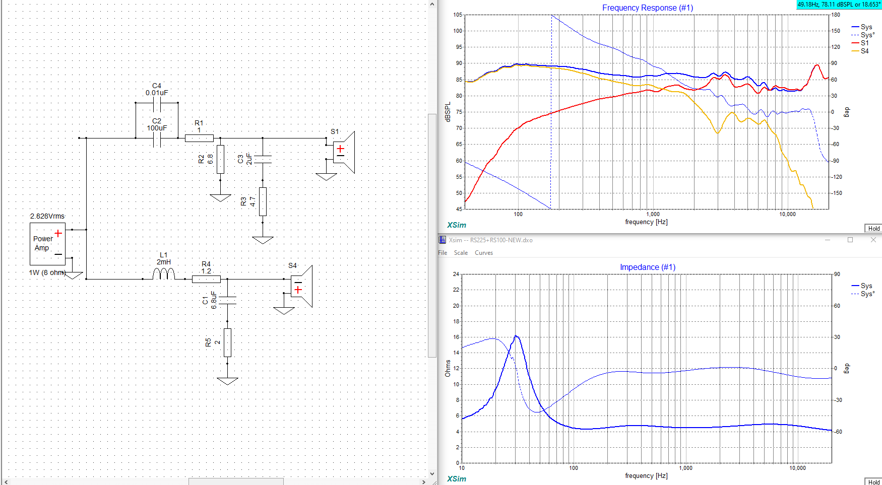
Your concerns about flipping the driver are valid. The short closed end is a “stub” designed to help cancel the reflection null at the TL exit. Typically we aim to put the driver at 20% to 33% of the way from the closed end to do this. But we won’t know how much it affects the response until we simulate it. Have not done that yet but it’s easy to do just need 10min. Bracing is always important if you have a span of wood more than 8in free. But it may not matter if you never play loud which is when pressure builds up. Regarding 4 ohms and 8ohms - I can only tell you what I have simulated as a crossover. If there is a simulation of a 4ohm woofer and 8ohm full range then the predicted impedance plot is what the amp sees. In general, this 1st order crossover is very benign. For the 8ohm it is 7ohms low for 20ohms high and smooth phase variations. I forget what the 4ohm looks like. I have the Miflex hot melted and zip tied now in the final xo on the TL. A member simulated a PS95-8 and RS225-4 with the same type of XO and got low of 4ohms and high peak of 16ohms. Very benign if your amp can handle 4ohms. Post 2252:
Last edited:
Your concerns about flipping the driver are valid. The short closed end is a “stub” designed to help cancel the reflection null at the TL exit. Typically we aim to put the driver at 20% to 33% of the way from the closed end to do this. But we won’t know how much it affects the response until we simulate it. Have not done that yet but it’s easy to do just need 10min.
Bracing is always important if you have a span of wood more than 8in free. But it may not matter if you never play loud which is when pressure builds up.
Regarding 4 ohms and 8ohms - I can only tell you what I have simulated as a crossover. If there is a simulation of a 4ohm woofer and 8ohm full range then the predicted impedance plot is what the amp sees. In general, this 1st order crossover is very benign. For the 8ohm it is 7ohms low for 20ohms high and smooth phase variations. I forget what the 4ohm looks like.
I have the Miflex hot melted and zip tied now in the final xo on the TL.
A member simulated a PS95-8 and RS225-4 with the same type of XO and got low of 4ohms and high peak of 16ohms. Very benign if your amp can handle 4ohms. Post 2252 (image deleted to save space)
Thanks, useful information as always. I believe you are using 8 ohms speakers in each position, correct?
An additional question - how does damping factor of the amp impact the sound of these speakers? Do they need a high damping factor to really make them sound their best, or are they really easy to drive and don’t need a lot of damping? You mentioned a Class A amp that sounded really good driving them, and I was wondering what the damping factor of that might be (for comparison). I ask because I will have two mono-block amps for each channel, but the damping factor will either be 5 or 20, depending on bridged vs parallel joining of the blocks. Any thoughts?
Oh, did you ever get a weight (even an estimate) on the speaker box weight? More or less than a big bag of water softener pellets? 8)
These sound great with a wide variety of amps because the impedance is relatively a flat 8ohms. The Alpha Nirvana is about a damping factor of 50 I think (at bass freq). I have used it with a Class AB and Class D. All good. Bass with FH9HVX or TPA3255 is about the same. What you need though is power. At least 50w and preferably 75w to 100w.
Weight of 3/4in BB ply version is (guessing) about 45 to 50lbs ea. They are easy to move though due to the vent acting as a handle.
Weight of 3/4in BB ply version is (guessing) about 45 to 50lbs ea. They are easy to move though due to the vent acting as a handle.
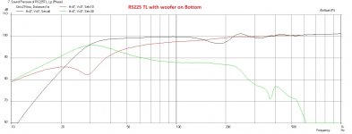
Effect of mounting woofer on top vs bottom
Here are the simulations of the RS225 TL with simply the positions of the woofer swapped with the full range (a 7in difference about). With the woofer on the bottom, the dip at 180Hz is great by about 1.5dB. Probably no big deal as this region is full of floor bounce dips and room reflections anyway. The sims are at 21Vrms. The location of the dip doesn't change with power. There is also more higher bandwidth stuff from the port output - but I don't think that is a problem.
Default top position:
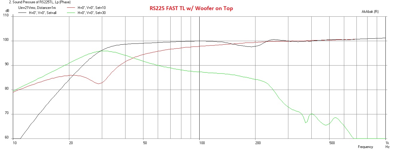
Bottom position:

Here are the simulations of the RS225 TL with simply the positions of the woofer swapped with the full range (a 7in difference about). With the woofer on the bottom, the dip at 180Hz is great by about 1.5dB. Probably no big deal as this region is full of floor bounce dips and room reflections anyway. The sims are at 21Vrms. The location of the dip doesn't change with power. There is also more higher bandwidth stuff from the port output - but I don't think that is a problem.
Default top position:
Bottom position:
Attachments
Everything is built, so I ordered X's PCBs for the crossovers. I have done a lot of point-to-point, but it never looks nearly as neat as a dedicated PCB. I'm mounting the crossovers externally on the back of the enclosure. I'd like to have easy access to the components if I decide to try a different FR driver that needs different value components. I'm even thinking about wiring in screw terminals in place of the components that would need to be changed. This way it would be a very quick change and I wouldn't need to solder, unsolder, solder, unsolder, etc.
Mike
Mike
I haven't put any finish on the enclosures yet, but there will be pics once I do so. If I manage to make the cross-over arrangement with screw terminals work, I'll post pics of them.
Cool, look forward to seeing them.
When I finally build my “real wood” TL‘s, I think I might do the same with the crossover. It would be very convenient to have it on the exterior to easily tweak.
When I finally build my “real wood” TL‘s, I think I might do the same with the crossover. It would be very convenient to have it on the exterior to easily tweak.
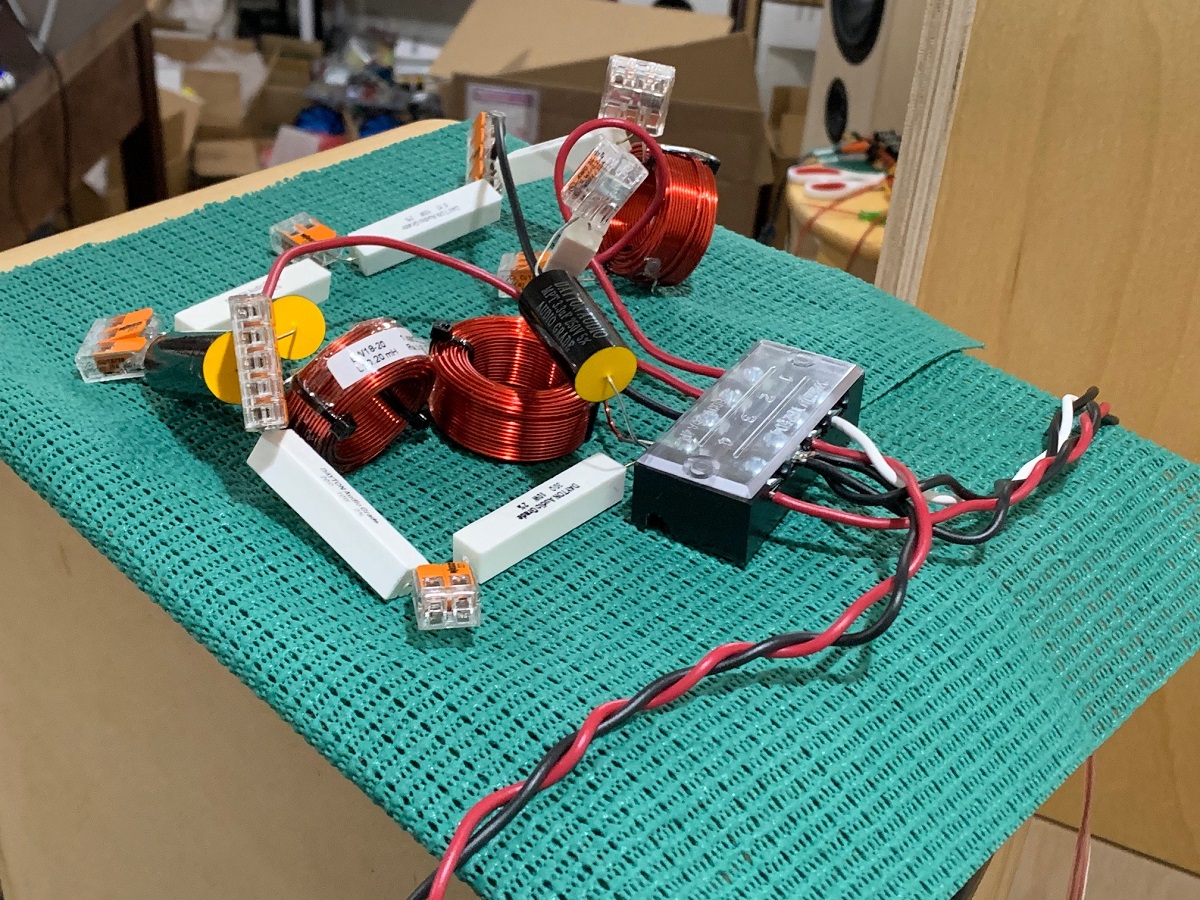
Good idea about screw terminals for the quick change. One thing JPS64 sometimes uses are riser pins with a Y yoke and you can solder the replacement part the riser. It might have better signal quality than a screw terminal. Wago connectors also work real well when I am making prototype crossovers. Like here:
Looking forward to seeing another 10F/RS225 FAST being born. Are you doing the sealed box or the TL?
Looking forward to seeing another 10F/RS225 FAST being born. Are you doing the sealed box or the TL?
Hi X,
I had the sealed boxes, but am going with the TLs now. I'm really looking forward to hearing them. The sealed boxes were great, so I'm sure these are also going to be great.
Mike
I had the sealed boxes, but am going with the TLs now. I'm really looking forward to hearing them. The sealed boxes were great, so I'm sure these are also going to be great.
Mike
+1 on the Wago connectors.
I bought a box of 3-way connectors.
Works great, but you have to take care to double check the signal paths it can quickly become a mess of parts and wires! 🙂
Well, I do have to at least triple check myself... I've never been great with electricity!
I bought a box of 3-way connectors.
Works great, but you have to take care to double check the signal paths it can quickly become a mess of parts and wires! 🙂
Well, I do have to at least triple check myself... I've never been great with electricity!
- Home
- Loudspeakers
- Full Range
- 10F/8424 & RS225-8 FAST / WAW Ref Monitor