I started reading your thread because I was interested in impressions/measurements of the the TG9FD10. BTW, is yours the 4 or 8 ohm versions?
Anyways... I've read through this whole thread and I think you have a very nice speaker there. Those are some high performing drivers so it's good to see that you are continuing to experiment and measure because they should be phenomenal when you get it nailed down.
If you don't mind a little help then I have a few ideas for you to help get it refined further (Some of this was suggested by 5th element earlier and you really should take his advice as he knows what he's talking about)
First of all, you really should try to hit your specific acoustic slopes. The minidsp is just dealing with the input/output signal. It's up to you to deal with the drivers actual response. The areas that deviate from the standard slope are messing with your frequency response and they should be dealt with on driver side eq, not global. Also, your xo should be exactly 6db down at the xo. No less, no more unless you're using butterworth.
I can't remember how to do it off the top of my head, but you can import standard slopes, ie. LR12 etc. into REW and then adjust your xo/driver eq and measure until you hit your desired slopes. That's how xo's are typically designed and how I do it, both digital and passive. If you have the interest and time, I recommend download passive crossover designer or something similar and spend some time playing with it. There is a learning curve and it'll seem complicated at first, but it'll help you understand what's going on. BTW, PCD has an active section too so you can model your dsp setting to hit slopes there too.
Secondly, you're using the RS225 too high. A 750 xo with 1st or 2nd order is just not going to work that great (2nd order maybe if you deal with the breakup) . Regardless of what your distortion measurements are telling you (you need to raise the level as stated before because at .71V you're not really getting any useful information in you distortion sweeps, you're mostly just seeing the noise floor)
I know you think it sounds great, but that's mainly because you likely haven't heard it sound the way it should. That's not a critisism, I used to think all my designs sounded great when I first set them up too. When people are saying that the female vocals sounds hard, that is likely due to the woofer's breakup. In the graph above, the breakup is only about 20db down. You're hearing that, and believe me, you don't want to hear the breakup on those dayton drivers. It should be at least 40db down, preferably 50.
I'd move the xo back down to around your baffle step frequency (450Hz?) and HIT YOUR SLOPES so that the crossover is actually where you expect it to be and the individual driver responses are 6db down where they cross. If you need to, use the peq function to add a notch or two at the woofers breakup so that it's at least 40db below the summed. And I would stick with 2nd order or higher. With 1st order slopes you are going to be introducing distortion at both ends (low on the 10F, high on the RS225)
Third, you have some phase issues going on. Anywhere where the individual driver's response is above the summed response you have phase cancellation. Looks like pretty much from 70-5K there are phase issues which are going to affect the frequency response and imaging. The drivers response should not go above the summed and you should have more gain around the crossover in the summed response than your measurements show.
Reverse the polarity of the 10F and measure. you should see a dip in the summed response at the xo. My guess is that you will see a minor dip at the xo and the response actually raising from 70-350 and around 2k. That's not what you want.
To make it right, with the 10F reversed and both drivers connected, measure and adjust the delay of the 10F only until you get a suckout of at least 20db or so. A second order LR xo should have a wide and deep notch, 4th order a narrow deep notch. When you get a deep notch, switch the polarity back to where you had it and measure. Hopefully the summed response is no longer below the individual responses.
Now, you'll likely see a hump at the xo because your current xo is not 6db down like it should be. To fix this either hit the correct target slopes as outlined above (recommended) or move your crossover points apart, ie 350Hz on the woofer and 450Hz on the mid.
Lastly, if it was me I would build a good solid enclosure out of wood or another solid material. The box contributes more than you think to the sound and will smear the image if it's resonating. Taking an impedance sweep should show you any problem areas.
This is easy and cheap to make: Impedance Measurement
I would also probably make the "dagger" enclosure extend to the back of the box and then vent outside with the point not quite closed. Stuff this lightly to get an aperiodic vent. This should give you a more open sound and will damp the 10F resonant peak if it's stuffed right.
Good luck!
Satx,
Thanks for the input and suggestions. Indeed 5th Element has some great suggestions. I am using the ScanSpeak 10F/8424 not TG9FD (that was tested just for grins at one point). I am currently running Butterworth 1st order and electrical XO is at 350Hz. Acoustically it is coming out closer to 600Hz to 700Hz, and I think that may have something to do with how I had to pad the 10F down by -6dB to level match the RS225 due to baffle step loss. Both the 10F and RS225 are class leading wide bandwidth units - you are not going to find a wider smoother response anywhere - so I think the reason the XO slopes are not textbook perfect is either cabinet related because there is baffle step going on and the Dagger imposes its own roll-off. I will work on applying EQ to the individual drivers first to get the right slopes and then work on the XO's to get them down to where I wanted them, at about 350 or 400Hz. With 1st order XO, reversing polarity maybe makes a 6dB suckout - not 20dB - that definitely occurs with the higher order XO like LR4. It's a work in progress but not sure why you think the phase is off - it it were that bad - the Step Response would not look like this, and I would not get anything resembling a square wave out of it. I did indeed consider a vented short TL for the Dagger to give it that more open sound - but the simulations in Akabak showed that it would cause a cancellation dip due to the sound coming out the back summing with the front. I did indeed measure all the impedances of the Dagger and the sealed box for the RS225 and they are quite good and don't indicate troubling resonances with the foam cabinet - it's in the thread if you look for it. Making the enclosure out of 18mm BB would be ideal of course, and I may go there with the assistance of a good cabinet maker in the future, but for now, I am limited with what I can build with at home given the no wood shop or real power tools limitation (table saw, router, belt sander, etc).
Last edited:
As I said in another thread, I am looking to make a low XO 2-way using an 8" woofer. I did buy a pair of the TC9's, but I don't think that it has the oats to keep up. Anyway.
The TC9 is designed to be used OB or IB. Your dagger is sort of IB. Another approach is to put it in a Qtc=1 box. Well, that would be ~ 700 liters! However, a 4" diameter 12" tube well stuffed with fiberglass gets roughly the same result. With the driver seeing a Q=1 box, you can then put an LR2 XO at roughly 200Hz and get and acoustic LR4. (You will need to play with the XO point to get the exact match.) There will be a slight overshoot at the driver cutoff, so satx's comments apply.
The same kind of thing can be done with the 10F, but now the Q=1 box ~14 liters, which I would do with a section of 6" pipe and a plywood cap. However, my same concern about max SPL applies.
Yet another approach is to ignore the telephone band restriction (which you have done) and put the XO up far enough that an electrical (DSP) LR2 actually produces an acoustic LR2. I did this for a customer using the Audax HM210C0 and the MA A7.3 at 700Hz. Customer wanted passive XO and a passive XO at 250Hz is prohibitively expensive. The Audax has a much more benign break-up than the RS225, so I didn't have to trap the break-up peak.
Bob
Last edited:
Cool that you are going to give the TC9FD a try. What is the reason you want a Q of 1 on the rear chamber? I thought 0.71 was the goal? And if you push Q below 0.71 it will be over damped - which is OK if you want cleaner and tighter dynamics. I measured my Q for the 10F and 1.1Liter Dagger and is 0.63 I think. Much smaller chamber that doesn't take hardly any room.
Satx,
Thanks for the input and suggestions. Indeed 5th Element has some great suggestions. I am using the ScanSpeak 10F/8424 not TG9FD (that was tested just for grins at one point). I am currently running Butterworth 1st order and electrical XO is at 350Hz. Acoustically it is coming out closer to 600Hz to 700Hz, and I think that may have something to do with how I had to pad the 10F down by -6dB to level match the RS225 due to baffle step loss. Both the 10F and RS225 are class leading wide bandwidth units - you are not going to find a wider smoother response anywhere - so I think the reason the XO slopes are not textbook perfect is either cabinet related because there is baffle step going on and the Dagger imposes its own roll-off. I will work on applying EQ to the individual drivers first to get the right slopes and then work on the XO's to get them down to where I wanted them, at about 350 or 400Hz. With 1st order XO, reversing polarity maybe makes a 6dB suckout - not 20dB - that definitely occurs with the higher order XO like LR4. It's a work in progress but not sure why you think the phase is off - it it were that bad - the Step Response would not look like this, and I would not get anything resembling a square wave out of it. I did indeed consider a vented short TL for the Dagger to give it that more open sound - but the simulations in Akabak showed that it would cause a cancellation dip due to the sound coming out the back summing with the front. I did indeed measure all the impedances of the Dagger and the sealed box for the RS225 and they are quite good and don't indicate troubling resonances with the foam cabinet - it's in the thread if you look for it. Making the enclosure out of 18mm BB would be ideal of course, and I may go there with the assistance of a good cabinet maker in the future, but for now, I am limited with what I can build with at home given the no wood shop or real power tools limitation (table saw, router, belt sander, etc).
Yes, I realize that you're using the 10F. I originally clicked on your thread because it popped up in a google search for the TG9FD
Try level matching the 10F to whatever the Dayton is at at around 350 or so. Then set the xo's. This might help get them closer to where you expect them to be. Your slopes do look pretty good and I'm sure this is a testament to the smooth native response of the drivers.
With a 1st order BW you're right, you probably won't end up with as deep a suckout with the polarity reversed, but I would hope for a little more than 6db. I'm not that familiar with 1st order though so YMMV. I did do a fast once with Fostex FF85wk and rs180-08 crossed at 450Hz second order on the dayton and 1st on the Fostex all passive. I found it necessary to use an aperiodic enclosure for the Fostex to control the peaking at FS. I really don't think you'll get any null from the minimal output from the rear. Remember that it's stuffed so you're really just controlling the pressure in the box. You're not creating an open mid tunnel.
Phase- once again, I think the phase is off because the summed response is below the individual driver responses at various areas above and below the crossover and you aren't getting any real gain at the crossover. This is a dead give away.
besides differing delay, this is most likely due to the BW6 crossover. They are just really hard to get right and the increased distortion above and below xo just makes them a poor choice most of the time. But, like I said, I've used it on a small driver crossed in pretty low with decent results so I'm not saying it doesn't work or you shouldn't use it.
I forgot that you had posted impedance plots. If you didn't see anything there and you're happy with the boxes then no problem, keep them. I really have no idea how that foam performs so you would know more than there.
BTW, are you using the 4 or 8 ohm version of the Dayton RS225? Either way, I think your sensitivity should be higher than 82db.
Did you stuff either box with anything? That will lower q slightly, but will help with reflections come back through the cone and standing waves within the enclosure.
What is the reason you want a Q of 1 on the rear chamber? I thought 0.71 was the goal?
Qbox cannot be lower than Qt. TC9 Qt=0.89
dave
Take a look at this regarding phase. I had these driver files already so I put together a quick sim. Dayton is the 4 ohm and 10F is 8 ohm, that's what I had already.
This is just to show what you should be seeing around the crossover in regards to summed FR vs individual driver FR. Notice the large combined gain in summed response from 80-1800Hz. Then notice the response above 2K where the woofer's breakup is out of phase with the 10F and causing cancellations. This is with one // notch, 2 series notches and an eliptical notch! And it still looks like poo. 1st order crossovers are almost never a cap and a coil, especially with metal drivers. I also had to boost the crap out of the 10F with active eq to get it to apoximate a 1st order slope below the crossover, but the baffle model on it might be set up for open baffle, I can't remember.
Gray line is reverse polarity on the mid. 13db down and the phase is not particularly good with the sim. I don't think 20db is out of the question. And notice how wide the notch is.
The other two show my attempt to hit 1st order slopes which wasn't particularly successful. But those targets are what yours should look similar to if you want true 1st order slopes.
Don't know if you saw post 150, Byrtt, who designed the passive XO's for me is showing how DSP can be used to get the text book slopes. I just have not had chance to try yet.
Don't know if you saw post 150, Byrtt, who designed the passive XO's for me is showing how DSP can be used to get the text book slopes. I just have not had chance to try yet.
I forgot about that.
Yes, it certainly can and that's what I was suggesting to you earlier. I didn't post those to try to get you to go passive. That sim I did is not very good. It's just to show phase and gain/cancellation.
That graph you just posted demonstrates the point I'm trying to make about your phase being off. Between 70 and 350 you are showing cancellation of the woofers response. You should instead see gain like you do at and above the xo.
RS225-8 is rated 88dB at 2.83v. Due to baffle step loss of narrow 10in wide baffle, the bass is only good for about 82dB. Matches my Akabak sim that includes effect of finite baffle width and reflections spot on. This prompted my earlier question of how speakers using drivers of similar sensitivity seem to get their overall speaker sensitivity to match driver rated value. I think Anthony Bisset said that companies typically quote sensitivity at 1kHz. If I did that, my sensitivity would be 88dB as well. If I had a TQWT or BLH, I could get the bass to have more gain than just the direct radiator. Perhaps then it would be closer to nominal driver rating. Perhaps it is because I am using sealed - and not bass reflex which is almost 98% of alignment used by commercial speakers nowadays.
The 82dB is indeed what I end up at for bass at 41Hz and I padded the 10F by -6dB to level match.
I suppose a dual parallel RS225-8 driven at 4ohms would by 88dB at 2.83v (2 watts).
The 82dB is indeed what I end up at for bass at 41Hz and I padded the 10F by -6dB to level match.
I suppose a dual parallel RS225-8 driven at 4ohms would by 88dB at 2.83v (2 watts).
Specs show 88.8 so almost 89. So you are at almost 7db of baffle step. 6 is full baffle step and usually that's too much. But it is something that has to be adjusted by ear to your space. Not saying it's right or wrong, I was just wondering.
You should not have a final system sensitivity of the woofers published rating, so it's right to be below that otherwise you would have a zero baffle step design which might be ok for in wall/near wall placement. If your putting them on stands away from the walls like you are then it should be lower overall like you have it.
They are often quoted at 1k, but if you look at manufacture's FR graph, it looks like about 89 to me all the way down. On your baffle I think you should have a -3db point at about 450Hz. So if you if your xo is in this range or a little lower, I would shoot for an overall sensitivity of about 85. But, maybe I'm missing something.
Usually a woofer with an 89 sensitivity would have a final overall sensitivity of around 85, but that's certainly not a hard rule. I usually use the sensitivity of the woofer at around 200-300 as a jumping off point to set mid/tweeter levels with a 10" baffle.
Specs show 88.8 so almost 89. So you are at almost 7db of baffle step. 6 is full baffle step and usually that's too much. But it is something that has to be adjusted by ear to your space. Not saying it's right or wrong, I was just wondering.
You should not have a final system sensitivity of the woofers published rating, so it's right to be below that otherwise you would have a zero baffle step design which might be ok for in wall/near wall placement. If your putting them on stands away from the walls like you are then it should be lower overall like you have it.
They are often quoted at 1k, but if you look at manufacture's FR graph, it looks like about 89 to me all the way down. On your baffle I think you should have a -3db point at about 450Hz. So if you if your xo is in this range or a little lower, I would shoot for an overall sensitivity of about 85. But, maybe I'm missing something.
Usually a woofer with an 89 sensitivity would have a final overall sensitivity of around 85, but that's certainly not a hard rule. I usually use the sensitivity of the woofer at around 200-300 as a jumping off point to set mid/tweeter levels with a 10" baffle.
Let me double check my drive voltage rms. It may be lower than what I think. It's been a while since I measured that as system may have drifted - especially since I am using different class AB amp on woofers and adjusted level to match.
Let me double check my drive voltage rms. It may be lower than what I think. It's been a while since I measured that as system may have drifted - especially since I am using different class AB amp on woofers and adjusted level to match.
Hey, if it sounds balanced to you that's all that matters. every room is different.
How are you measuring the bass response? are you splicing near field and far field or what?
As I said in another thread, I am looking to make a low XO 2-way using an 8" woofer. I did buy a pair of the TC9's, but I don't think that it has the oats to keep up. Anyway.
The TC9 is designed to be used OB or IB. Your dagger is sort of IB. Another approach is to put it in a Qtc=1 box. Well, that would be ~ 700 liters! However, a 4" diameter 12" tube well stuffed with fiberglass gets roughly the same result. With the driver seeing a Q=1 box, you can then put an LR2 XO at roughly 200Hz and get and acoustic LR4. (You will need to play with the XO point to get the exact match.) There will be a slight overshoot at the driver cutoff, so satx's comments apply.
The same kind of thing can be done with the 10F, but now the Q=1 box ~14 liters, which I would do with a section of 6" pipe and a plywood cap. However, my same concern about max SPL applies.
Yet another approach is to ignore the telephone band restriction (which you have done) and put the XO up far enough that an electrical (DSP) LR2 actually produces an acoustic LR2. I did this for a customer using the Audax HM210C0 and the MA A7.3 at 700Hz. Customer wanted passive XO and a passive XO at 250Hz is prohibitively expensive. The Audax has a much more benign break-up than the RS225, so I didn't have to trap the break-up peak.
Bob
If you need more oomph on the top end, look at PRV 5MR450NDY. About 95dB and can take 225watts. XO above 300Hz. Very low distortion but has a few peaks that can use a little taming. Goes up to 15kHz - may be lacking for some but I don't miss what I can't hear.
Thread evolving thanks all supporting it its very educating and interesting, Bob Brines hat off you try TC9FD time will tell if you like it and it get it from workshop to livingroom.
BW1 XO with possibility being transient perfect i understand X want investigated for a while because as is think he knows what he hears sounds good and there could be more precision to improve further. My post 63/106 exercise running BW1 at 400Hz for me performed very good and now the tweeter is replaced with a 10F/8424, acoustic slope plus squarer waves on axis that TC9FD can be seen below and sound was very good.
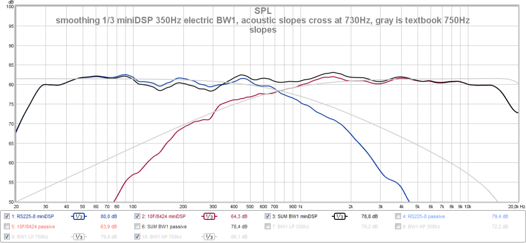
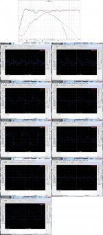
Being little green this sport making good acoustic XO integration observed a lot of things happen when trying calibrate speaker to hit best possible performance and these some times in head got confusing leading to wrong settings. So for better understanding made som small study in electric domain with target BW1 XO slopes. The filters are set real in JRiver DSP engine then soundcard I/O looped back and REW listen in loop.
Frequency response HP/LP BW1 730Hz and their sum if slopes are perfect. The boosts and cuts are when drivers are unaligned on axis and for this example 0,09mSec delay where blue is woofer set behind and red if tweeter set behind. The alignment offset effect is nice to see visual to be prepared when setting up system. Setting higher offsets really spoils things getting much worse than the ones shown here.

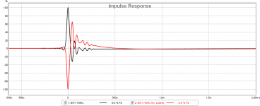
Impulse response dicovered the ringing at pulse decay is because of sytems LP in this exercise set at 18,5kHz BW2 plus soundcards limit. If the 18,5kHz BW2 system LP filter was deactivated the black impulse presenting sum gets as pure on pulse decay side as on attack side of pulse. Probably some the reason modern tweeters have HF extension up very high and reflect in better squarer wave reproduction too.

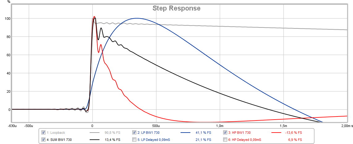
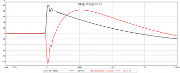
Step response exercise discovered some logic too and help align offset LP and HP sections and for below example same offset 0,09mSec is used. Black is perfect sum LP and HP summed and again system LP at 18,5Khz shows up preventing strait line from decay slopes meeting at 100% step pulse forming a sharp pinch. Blue is woofer set behind and red is tweeter set behind. Tweaking a digital delay up and down get blue or red in synch with the correct black one, if setting high values as offset things get really ugly. Running digital DSP powered exercise in electric domain its easy to say black slope reflect perfect slope for this alignment but its mush worse in reality when one gets close to target to see if slope has some small deviation. For that in reality did find if one measure woofer with its lowpass filter turned off and save this measurement as target then tweak summed measurement to overlay with target.
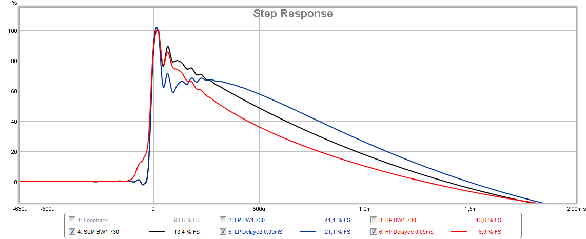
Step response once again this time to see the two aligned signals blue LF and red HF they sum as black system step response. Grey is soundcard loopback having nice lower frequency extension than the drivers.
Hope some find usefull when setting up BW1 filter.
BW1 XO with possibility being transient perfect i understand X want investigated for a while because as is think he knows what he hears sounds good and there could be more precision to improve further. My post 63/106 exercise running BW1 at 400Hz for me performed very good and now the tweeter is replaced with a 10F/8424, acoustic slope plus squarer waves on axis that TC9FD can be seen below and sound was very good.
Being little green this sport making good acoustic XO integration observed a lot of things happen when trying calibrate speaker to hit best possible performance and these some times in head got confusing leading to wrong settings. So for better understanding made som small study in electric domain with target BW1 XO slopes. The filters are set real in JRiver DSP engine then soundcard I/O looped back and REW listen in loop.
Frequency response HP/LP BW1 730Hz and their sum if slopes are perfect. The boosts and cuts are when drivers are unaligned on axis and for this example 0,09mSec delay where blue is woofer set behind and red if tweeter set behind. The alignment offset effect is nice to see visual to be prepared when setting up system. Setting higher offsets really spoils things getting much worse than the ones shown here.
Impulse response dicovered the ringing at pulse decay is because of sytems LP in this exercise set at 18,5kHz BW2 plus soundcards limit. If the 18,5kHz BW2 system LP filter was deactivated the black impulse presenting sum gets as pure on pulse decay side as on attack side of pulse. Probably some the reason modern tweeters have HF extension up very high and reflect in better squarer wave reproduction too.
Step response exercise discovered some logic too and help align offset LP and HP sections and for below example same offset 0,09mSec is used. Black is perfect sum LP and HP summed and again system LP at 18,5Khz shows up preventing strait line from decay slopes meeting at 100% step pulse forming a sharp pinch. Blue is woofer set behind and red is tweeter set behind. Tweaking a digital delay up and down get blue or red in synch with the correct black one, if setting high values as offset things get really ugly. Running digital DSP powered exercise in electric domain its easy to say black slope reflect perfect slope for this alignment but its mush worse in reality when one gets close to target to see if slope has some small deviation. For that in reality did find if one measure woofer with its lowpass filter turned off and save this measurement as target then tweak summed measurement to overlay with target.
Step response once again this time to see the two aligned signals blue LF and red HF they sum as black system step response. Grey is soundcard loopback having nice lower frequency extension than the drivers.
Hope some find usefull when setting up BW1 filter.
Attachments


Last edited:
Very nice study on the things that affect step response! I never would have guessed that the bass and tweeter look like that before they combine to make a triangle step. You have some really high quality signals there presented.
Thanks!
Can you hear a difference between the blue black red versions of the step response when playing music? Is the black one clearly superior?
Thanks!
Can you hear a difference between the blue black red versions of the step response when playing music? Is the black one clearly superior?
Very nice study on the things that affect step response! I never would have guessed that the bass and tweeter look like that before they combine to make a triangle step. You have some really high quality signals there presented.
Thanks!
Can you hear a difference between the blue black red versions of the step response when playing music? Is the black one clearly superior?
Yes cleared some things for head to get stuff visual and less user errors when trimming system.
Difference is very clear under critical listening when being tecnical correct placed on axis between blue black red versions. One must then admit if sitting a strange position in room the the 0.09mSec aprox. 3 cm shown think can easy be a actual offset. The red one cover the midrange boost that ruined our first trial for passive.
That said its as when correct aligned they fire sound stream more as a concentrated hot beam not spreading sound so much to room reflections but i could be too practical simple thinking in what really happens.
A fun thing at post 63 my woofer is clear set back being as the red and settings was 0.63 now its 0,36mSec, yours seems as blue where tweeter needs set back, so try measure woofer alone with all correction you have set at it just turn off the LP XO then one get a nice target slope to hit when fine trimming offset. If it don't work your setup because electric XO doesn't reflect acoustic XO then request my mdat file in that it is set at 730Hz.
REW was warmed up so reversed polarity one driver at BW1 and it doesn't reflect in FR looking for deep nulls. Phase takes a 180º turn ruin step response and looked for other clues to align acoustic phase in this mode maybe some could find schemes in SR patterns to look for i find it hard the few trials.
Attachments


Yes cleared some things for head to get stuff visual and less user errors when trimming system.
Difference is very clear under critical listening when being tecnical correct placed on axis between blue black red versions. One must then admit if sitting a strange position in room the the 0.09mSec aprox. 3 cm shown think can easy be a actual offset. The red one cover the midrange boost that ruined our first trial for passive.
That said its as when correct aligned they fire sound stream more as a concentrated hot beam not spreading sound so much to room reflections but i could be too practical simple thinking in what really happens.
A fun thing at post 63 my woofer is clear set back being as the red and settings was 0.63 now its 0,36mSec, yours seems as blue where tweeter needs set back, so try measure woofer alone with all correction you have set at it just turn off the LP XO then one get a nice target slope to hit when fine trimming offset. If it don't work your setup because electric XO doesn't reflect acoustic XO then request my mdat file in that it is set at 730Hz.
REW was warmed up so reversed polarity one driver at BW1 and it doesn't reflect in FR looking for deep nulls. Phase takes a 180º turn ruin step response and looked for other clues to align acoustic phase in this mode maybe some could find schemes in SR patterns to look for i find it hard the few trials.
Byrtt, did you build the same speaker with these drivers?
If you reversed polarity you should see a null at the crossover point and at least a couple of octaves each side with BW1. Phase and step and everything else will get out of wack of course
- Home
- Loudspeakers
- Full Range
- 10F/8424 & RS225-8 FAST / WAW Ref Monitor