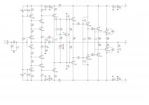
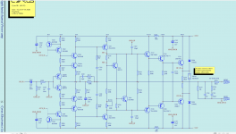
0,0158% - 20 кГц 8 Ом 50 Вт
Attachments
Last edited:
0,0158% - 20 кГц 8 Ом 50 Вт
Astaro, you're makes progress in topology design, it's very good


What transistors in the TO-3 package can be used at the output of the APEX AX17 amplifier ???
hi every body
i need an mute circuite for b80 apex amp without hiss and noise
and a short protection too
any body have any sugestion ?
thank you
.jpg")
i need an mute circuite for b80 apex amp without hiss and noise
and a short protection too
any body have any sugestion ?
thank you
Hi Guy's,
Seeing as this thread is about the ultimate fidelity amplifiers. Have you guys seen the Wolverine amplifier.
We have tested it and recorded 0.000027% THD at 1khz driving 80wrms into a 8 ohm load.
Link to the project in my signature.
Seeing as this thread is about the ultimate fidelity amplifiers. Have you guys seen the Wolverine amplifier.
We have tested it and recorded 0.000027% THD at 1khz driving 80wrms into a 8 ohm load.
Link to the project in my signature.
If your asking me. That's not the purpose of my post. The purpose is to let members who are subscribed to this thread know that there are other high fidelity amplifier designs on this forum. When I first joined the DiyAudio forum I thought this was the main thread that was discussed high performance aufio circuits. So this is not a sales pitch this is more a FYI.sales stopped? -))
Here is nice PCB Design For APEX A-Class PSU that uses single layer PCB, have CRC snubbler to suppress toroidal ringing, full bridge rectifier and CRC filtering for smooting and PSRR on 50Hz to be minimal, using A-Class from APEX circuit to provide low noise, high PSRR, low impendance out and routed for audio circuit.
Hi, @ronovar Can you or anyone here please suggest changes to this PSU to have a 5V output ?? This seems very good for a Pie based DAC that I want to power. Thanks in advance
Thanks X,
Thanks X.
Yes FH-9 hvx is on my build list too. I have posted both stereo version and mono version on this thread. Some members have built it too and very happy with it.
meanwhile, here is the final compact double sided pcb version of the APEX FX-8 amp. I have a few pairs of original renesas lat fets, might use them here.
Hi everybody!
I am currently building the FH9HVX (what a beautiful board!) but I am more than curious about it’s predecessor, the FX-8. Given the scarcity of lateral MOSFETS, does anybody know if the Exicon ECX 10N20/10P20 or ECW 20N20/20P20 are good substitutes?
https://www.profusionplc.com/type/lateral-mosfet
Best,
Anand.
https://www.profusionplc.com/parts/ecx10p20
https://www.profusionplc.com/parts/ecx10n20
scroll down full description:
"The ECX10N20 is a suitable replacement, substitute or equivalent for the 2SK1058"
"The ECX10P20 is a suitable equivalent, replacement or substitute for the 2SJ162"
https://www.profusionplc.com/parts/ecx10n20
scroll down full description:
"The ECX10N20 is a suitable replacement, substitute or equivalent for the 2SK1058"
"The ECX10P20 is a suitable equivalent, replacement or substitute for the 2SJ162"
Super! Thanks.https://www.profusionplc.com/parts/ecx10p20
https://www.profusionplc.com/parts/ecx10n20
scroll down full description:
"The ECX10N20 is a suitable replacement, substitute or equivalent for the 2SK1058"
"The ECX10P20 is a suitable equivalent, replacement or substitute for the 2SJ162"
Best,
Anand.
In Post #14024 on Prasi’s redrawn schematic of the FX-8, can somebody clarify the value of the pot (RV18)? I am assuming it is 1K (reviewing posts from pages 308-310, where Prasi replaced the 1N4007 diode with a trimmer, and it appears that a 500R trimmer should be enough). Where are we measuring bias? Across the resistor in a CRC supply or temporarily place a small value resistor on the voltage rails before the MOSFET stage?
Thanks,
Anand.
Thanks,
Anand.
Hello Anand,
put a 10 Ohm/5-10W in +,- rail to the bord. It's done in the DX Blame Amp.
Across the resistor you mesure bias to say 1V gives 100mA.
The Sonal 50x50 mm Board rerouted with doublesided power traces
could also be pcb option.
I could not listen diffrences between SK/SJ types and Exicons.
Goodluck with your build.
Hello
have searched again.
These based on Sonal Kunal Board 50 x 50mm.
https://www.diyaudio.com/community/threads/100w-ultimate-fidelity-amplifier.164093/post-4633690
https://www.diyaudio.com/community/threads/100w-ultimate-fidelity-amplifier.164093/post-4635579
https://www.diyaudio.com/community/threads/100w-ultimate-fidelity-amplifier.164093/post-4605857
https://www.diyaudio.com/community/threads/100w-ultimate-fidelity-amplifier.164093/post-4717772
https://www.diyaudio.com/community/threads/100w-ultimate-fidelity-amplifier.164093/post-4718454
Anand, if you not have, please read and scroll about from page 310 and you will find needed informations.
Any sucessful builds by experienced members.
Wish ALL a enjoyable XMas.
- Home
- Amplifiers
- Solid State
- 100W Ultimate Fidelity Amplifier