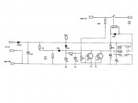
Easier just to think of it as drivers tied to the output then same way the finals are, and not as feedback as such in this case when comparing the two.
The amplifier with drivers connected to output will work fine (alot less power) even when finals are removed.
The amplifier with drivers connected to each other loose global negative feedback if finals are open circuit.
The Yamaha parent amplifier uses the 2nd picture with the emitter attached to each other.
Either way has its merits.
Has there been a change to the 2k2 ballast resistor for the 10k thermistor?
Mine has to get way to hot before it activates.
I'll try 3k3 and report back, but will save time if anyone knows if there has been a change.
What would a good temperature to trip the protection be?
Regards
Mine has to get way to hot before it activates.
I'll try 3k3 and report back, but will save time if anyone knows if there has been a change.
What would a good temperature to trip the protection be?
Regards
Attachments
Last edited:
There is no standard temperature V resistance response curve for cheap, ceramic thermistors so it may be just as easy to look at (i.e. test) the resistance of a few thermistors at different temperatures or try different styles/brands in the circuit for best results.
The trip temperature requirement of the thermistor itself will vary with its proximity to a hot heatsink or device you are monitoring but you would not like to touch a heatsink that reached >60C. Nor would you like your PCB to get that hot for any period of time.
65C on a heatsink surface would be a sensible trip temperature for any electronics exposed to personal contact. DIYs never stop tinkering so you can assume that applies universally to all projects. Commercial products may well run hotter than 60C but that is usually a carefully tested design risk that applies only to specific components, layout and expected use.
I have a friends Traynor Mono Block Bass guitar amp that is defective and not worth repairing. It had 325W in 2ohm capability.. I've removed amp board and O/P devices. The preamp tone board is repairable..
I'd want to install a new amp board, and use 3 x TO-3 Transistors on the original heat sinks That are on each end of the chassis.
Could the A40 be used into 2 Ohms with available TO-3's? I have 5 X A-40 PCB's, version with 6 output Transistors. The one extra odd number PCB would have a home..
If A40 can be used with some changes, to be determined later, I would simply secure the the purchase of the output devices.
Any thoughts, please?
Hello Friends
There are so many Apex amplifiers and variations. Can you suggest which of these amps are best for 100 to 120 watts.
There are so many Apex amplifiers and variations. Can you suggest which of these amps are best for 100 to 120 watts.
Hello friends.
I present to you the most muscular A40.
It took 2 years of work.
Apex A40 - Powerful monoblocks in bridge mode - Google Photos
I present to you the most muscular A40.
It took 2 years of work.
Apex A40 - Powerful monoblocks in bridge mode - Google Photos

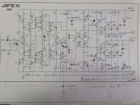
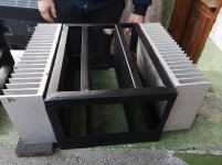
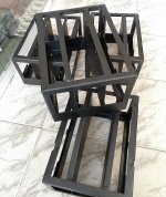
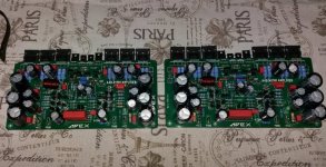
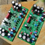
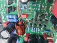
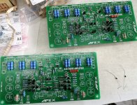
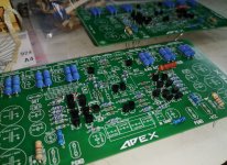
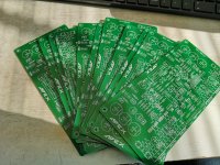
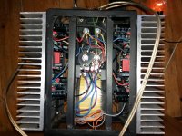
Here I enclose some photos from the process of construction and revival.
Each block has 2 bridge boards.
The current at rest is 600mA.
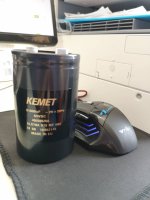
Each board is a separate arm, with each arm equipped with 91,000 uf in the face of Kemet.
The total capacity of the amplifier is 360,000 uf.
Each block has 2 bridge boards.
The current at rest is 600mA.
Each board is a separate arm, with each arm equipped with 91,000 uf in the face of Kemet.
The total capacity of the amplifier is 360,000 uf.
Attachments
-
 573b0c90da42.jpg211.3 KB · Views: 403
 -
 61035391b885.jpg262.3 KB · Views: 371
 -
 15bbe26ef2c8.jpg132.4 KB · Views: 393
 -
 63f231d8988e.jpg203.5 KB · Views: 468
 -
 2cff78552f2a.jpg749.6 KB · Views: 511
 -
 20201226_140717.jpg498.5 KB · Views: 805
 -
 f682d830cac6.jpg756.8 KB · Views: 802
 -
 e066491b4a60.jpg562.9 KB · Views: 849
 -
 752478a9cccd.jpg953.3 KB · Views: 942
 -
 ad641e1528c6.jpg243.2 KB · Views: 481
I don't have pictures of the final arrangement of the blocks, only those from the revival.
Finally, the power supply is with thick busbars and cables.
Finally, the power supply is with thick busbars and cables.
Not at the moment, because there is no need.
I play the monoblocks one after the other, not together.))))
I turn on one, the lights blink, then the other, blink again.
By the way, I forgot to say that there is no protection in the signal path.
There is protection that burns the fuses if something happens, and protects the speakers
No electricity, no problem))))
Very good! And when you turn it on, you can not hear extraneous sounds in the speaker systems?
Here I enclose some photos from the process of construction and revival.
Each block has 2 bridge boards.
The current at rest is 600mA.
Each board is a separate arm, with each arm equipped with 91,000 uf in the face of Kemet.
The total capacity of the amplifier is 360,000 uf.
😉🙂 great job very cool .
Thanks for the kind words.
I want to share with you what speakers I make especially for these A40s.
I apologize in advance for the deviation, but I think you will find it interesting.
?????? ?????? - Google Photos
?????? ?????? - ??? - Google Photos
If you are interested in drivers, I can talk about them.
Regards!
I want to share with you what speakers I make especially for these A40s.
I apologize in advance for the deviation, but I think you will find it interesting.
?????? ?????? - Google Photos
?????? ?????? - ??? - Google Photos
If you are interested in drivers, I can talk about them.
Regards!
- Home
- Amplifiers
- Solid State
- 100W Ultimate Fidelity Amplifier