Sicstock has them. No stock at Mouser, Digikey and Newark.
see if you can order them directly from onsemi.... they hand out 5 trannies each for 20 usd shipping.
At a time you can order 50 ( 5x10 of different model) trannies for 20 USD. worth a try.,
At onsemi it shows large min quantities. Thanks. I'm making up an order for Mouser..
Last edited:
thats great, iam planing to make sr100 but bc550 and bc560 are not available anywhere in market. can i use 5401 and 5551? or i should use anyother.
He brother you can use bc 547. Bc557. And others many options but check pinout ..I think sr200 is unbearable amplifier sound .very beautiful
Hello sir
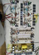
Hello Tarry sir .I have Also pair bc550 560 in sr 200 .I made 5 pcs borad .3 board bc547 bc557 .2 board bc 550 bc 560 .but all sound same
Hello Tarry sir .I have Also pair bc550 560 in sr 200 .I made 5 pcs borad .3 board bc547 bc557 .2 board bc 550 bc 560 .but all sound same
Attachments
Last edited:
Hello Tarry sir .I have Also pair bc550 560 in sr 200 .I made 5 pcs borad .3 board bc547 bc557 .2 board bc 550 bc 560 .but all sound same
Hi Sunny,
I'm sure BC547/557 will work fine. I was just showing a place that still have the BC 550/560 in stock.
Blessings, Terry
Has anyone made a surface mount version of any of these amplifiers.
I was thinking of making a AX14p just as a practice on SMD stuff. With 0805 being the smallest I want to hand solder. Using a double sided PCB.
But need some help choosing SMD versions of the components if anyone is willing to help out.
So obviously need to decide on small signal transistors, VAS/CCS Drivers, But still using Through hole power transistors. Will all resistors be SMD, what power rating (physical size) etc.
Regards
Attachments
Apex specifies power of resistors, rest resistors are all 0.25W, so 1210 package works and slightly easier to solder. dont know if R18/20 have to be 0.5W, a sim file would help.
for 2 or 3 watters, you can parallel 2512 types.
diodes can be easily found in smd version.
MMBT5401 and MMBT5551 for 2n5401/5551
for bc547/557 ---- bc847 /857 https://assets.nexperia.com/documents/data-sheet/BC849_BC850.pdf
dont know if mje340/350 2sc4793/2sa1837 have smd equivalent... these can be kept THT.
elco THT caps on top and SMD npo caps on bottom.
this should work unless apex / someone has some other suggestion.
Last edited:

MJE340 / 350 -> MJD340 / 350 but be aware of good heat dissipation, which in this case may cause an undesirable increase in the PCB area and may be better to stay to THT and leave MJE / 2Sx?

Has anyone made a surface mount version of any of these amplifiers.
I was thinking of making a AX14p just as a practice on SMD stuff. With 0805 being the smallest I want to hand solder. Using a double sided PCB.
But need some help choosing SMD versions of the components if anyone is willing to help out.
So obviously need to decide on small signal transistors, VAS/CCS Drivers, But still using Through hole power transistors. Will all resistors be SMD, what power rating (physical size) etc.
Regards
You can also use MELF resistors.
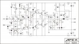
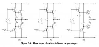
Who can tell me why there is a feedback connection in this place, I saw several similar amplifiers with a triple at the output, it was not there. It was like the second picture. What is the best and correct way to connect drivers to feedback or not?
Attachments
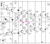
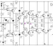
Who can tell me why there is a feedback connection in this place, I saw several similar amplifiers with a triple at the output, it was not there. It was like the second picture. What is the best and correct way to connect drivers to feedback or not?
According to Douglas Self's explanation:
"Figure 6.4a shows the most prevalent version (Type I), which has its driver emitter resistors connected to the output rail.
The Type II EF configuration in Figure 6.4b is at first sight merely a pointless variation on Type I, but in fact it has a valuable extra property. The shared driver emitter resistor Rd, with no output-rail connection, allows the drivers to reverse-bias the base – emitter junction of the output device being turned off. Assume that the output voltage is heading downwards through the crossover region; the current through Re1 has dropped to zero, but that through Re2 is increasing, giving a voltage drop across it, so Q4 base is caused to go more negative to get the output to the right voltage."
Nevertheless, worth to build the amplifier as it shared. APEX amplifiers built by many, and good sounding circuits as they are.
Attachments
Last edited:
Yes, I did Apex-14, 17, 20 and soon, I hope I will do A40. It simply seemed that if you tear these resistance from feedback, would be better ... because of it, i have asked. But there is some questions:
1. Will it be unambiguous better?
2. Will there be no instability from this?
PS^ My PCB^ Privalov Oleg Leonidovich's Profile - Engineer - PCBWay Community
1. Will it be unambiguous better?
2. Will there be no instability from this?
PS^ My PCB^ Privalov Oleg Leonidovich's Profile - Engineer - PCBWay Community
Last edited:
- Home
- Amplifiers
- Solid State
- 100W Ultimate Fidelity Amplifier