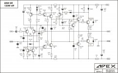
hi apex sir and everyone. in post 1 sch of ax 14 r2 and r8 right or in post 253 layout is right because in layout 22k resistance in place of 560r and 560r in place of 22k .which is right please tell me.
Read post #10 where someone points out that the values have been deliberately swapped.
R2 is 22k, R8 560.
Attachments
hi apex sir and everyone. in post 1 sch of ax 14 r2 and r8 right or in post 253 layout is right because in layout 22k resistance in place of 560r and 560r in place of 22k .which is right please tell me.
In sch post #1 R2 and R8 are reverted
Another ax-14 gerbers
Hello my friends!
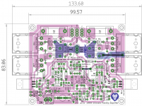
I have also made a simple AX-14 board. Could you please look at it, to see if there are any errors, or things I could do better?
EDIT: The drill files created are wrong, all drill holes are the same.. so this is 100% wrong. I will correct it in V02.
Attention!!! This board is not working! I do not take responsabilities if you make them and it doesn't work!
If I'm finished, I can post final gerbers of course 🙂
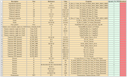
I also attached the BOM from which my build can be done.
Thanks for your help!
Hello my friends!
I have also made a simple AX-14 board. Could you please look at it, to see if there are any errors, or things I could do better?
EDIT: The drill files created are wrong, all drill holes are the same.. so this is 100% wrong. I will correct it in V02.
Attention!!! This board is not working! I do not take responsabilities if you make them and it doesn't work!
If I'm finished, I can post final gerbers of course 🙂
I also attached the BOM from which my build can be done.
Thanks for your help!
Attachments
Last edited:
Has anyone made the HV250?
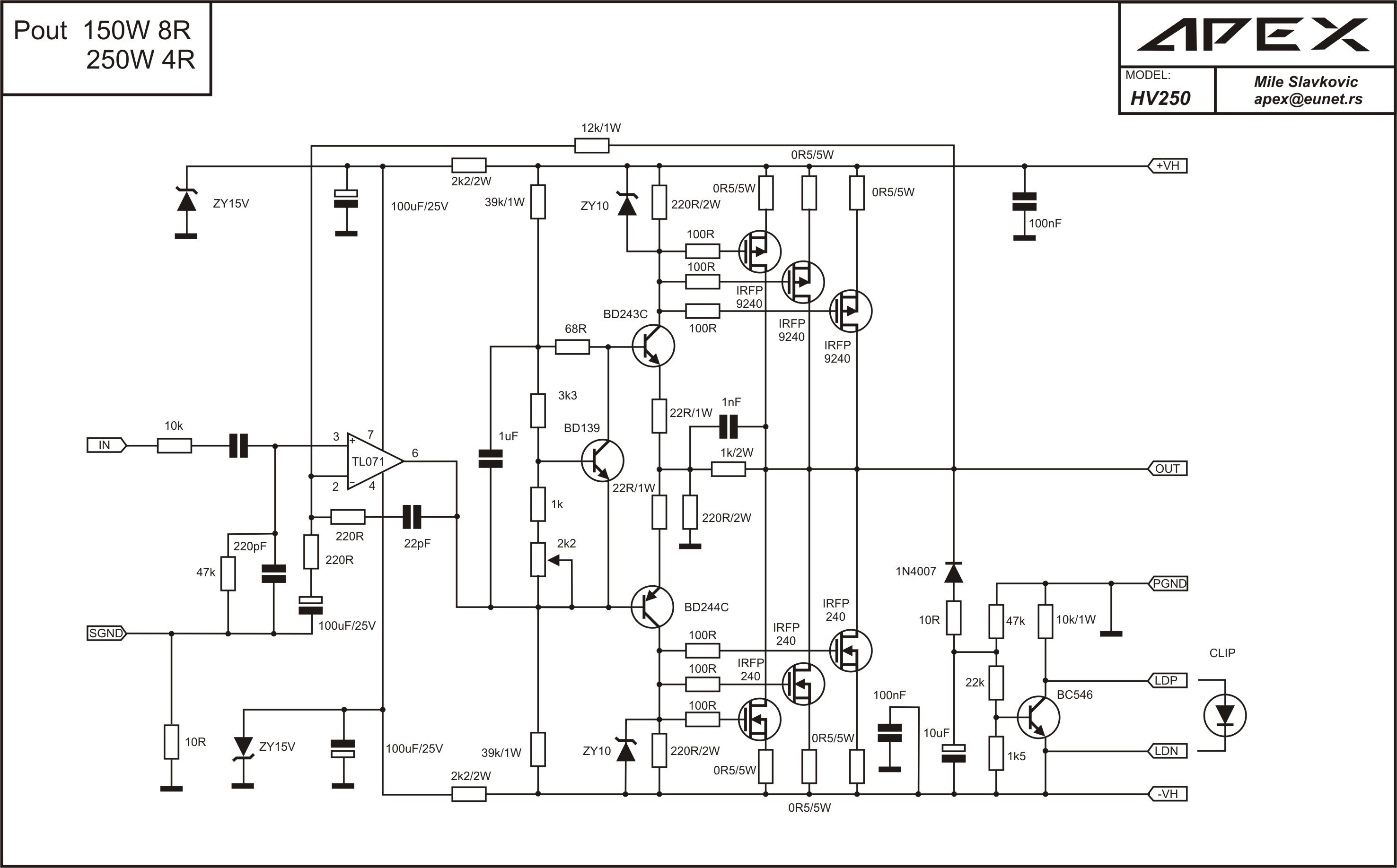
Yes I did it, but this is not a correct place to talk about it 🙂. It sholud be in MOSFET Amplifier IRFP240/IRFP9240, page 98 #975, there you can find the pcb that works properly.
hola prasi me puedes enviar en .pdf ax14 2pares
gracias
Hi,
please find attached herewith pdf files and other documents.
Attachments

 Lom, please note that diyAudio is an English language forum. Please post in English or at least provide a translation.
 Thank you..
Lom, ten en cuenta que diyAudio es un foro en inglés.
Por favor publique en inglés o al menos proporcione
una traducción. Gracias..
Hi APEX !
I'm doing ax14 pcb, and my transformer has 35-0-35 V. Can I use AX14 to drive 4 ohm loads with that transformer?
I'm doing ax14 pcb, and my transformer has 35-0-35 V. Can I use AX14 to drive 4 ohm loads with that transformer?
Hi APEX !
I'm doing ax14 pcb, and my transformer has 35-0-35 V. Can I use AX14 to drive 4 ohm loads with that transformer?
Hi, with 35v-0-35v AC, you gona have 48v-0-48v DC. For 4 ohm, it should be 45v-0-45v DC, but try it. What is the propose of this amplifier? Is for home listening only?
Hi APEX !
I'm doing ax14 pcb, and my transformer has 35-0-35 V. Can I use AX14 to drive 4 ohm loads with that transformer?
It would be safer to use 2 pairs of o/p devices with those voltages. See my design 100W Ultimate Fidelity Amplifier post # 10749
- Home
- Amplifiers
- Solid State
- 100W Ultimate Fidelity Amplifier