It is long ago. I do not think 50k is a good idea. If I remember correctly, the pot is in the feedback loop. I do not know how it changes the gain.
Also may be that the potentiometer has to be mounted on the copper side to gets louder when turning to the right. Sorry for incomplete information.
Also may be that the potentiometer has to be mounted on the copper side to gets louder when turning to the right. Sorry for incomplete information.
can i substitute the pot.5k with 50k because in my country this part is so hard to find it.
i am sorry my bad english.
regard mantrieSolder
You can not use 50k for A2 preamp but you can use it with TB1 preamp.
Hello Mr. Mile, I sent you an e-mail, but you did not answer.
I want to make a button switch on the amplifier, in the network found this board:
APEX_on_off.JPG — Yandex.Disk
I did not find the circuit schematic, so I drew from the board. Is the circuit correctly formed?
APEX ON_OFF Schematic.GIF — Yandex.Disk
Used this PCB:
APEX ON_OFF LAY6.GIF — Yandex.Disk
APEX ON_OFF LAY6 FOTO.GIF — Yandex.Disk
Result:
1. When i turn on 220V - immediately turns on the load, and the LED is very dim, I probably replace the 1k resistor on the 510R.
2. When I press the button is with an interval of 5 seconds - an uncertain switching, may turn on, or it may not turn on.
3. The transistor BD241 is heated. Does he need a radiator?
Tell me please how correctly the circuit should work, if I drew it circuit schematic correctly, and how to achieve a stable switching?
I'm sorry for my bad english.
I could not add pictures, so I inserted links.
Last edited:
Hello Mr. Mile, I sent you an e-mail, but you did not answer.
I want to make a button switch on the amplifier, in the network found this board:
APEX_on_off.JPG — Yandex.Disk
I did not find the circuit schematic, so I drew from the board. Is the circuit correctly formed?
APEX ON_OFF Schematic.GIF — Yandex.Disk
Used this PCB:
APEX ON_OFF LAY6.GIF — Yandex.Disk
APEX ON_OFF LAY6 FOTO.GIF — Yandex.Disk
Result:
1. When i turn on 220V - immediately turns on the load, and the LED is very dim, I probably replace the 1k resistor on the 510R.
2. When I press the button is with an interval of 5 seconds - an uncertain switching, may turn on, or it may not turn on.
3. The transistor BD241 is heated. Does he need a radiator?
Tell me please how correctly the circuit should work, if I drew it circuit schematic correctly, and how to achieve a stable switching?
I'm sorry for my bad english.
I could not add pictures, so I inserted links.
Circuit is correct. Use n.o. push button switch. BD241 must be hot no need to use heatsink.
Yes, I'm using n.o. push button switch. I do not know how to overcome the instability of switching, and rattling contacts relay.
Yes, I'm using n.o. push button switch. I do not know how to overcome the instability of switching, and rattling contacts relay.
Switching is stable in this circuit, something must be wrong in your build.
need help about AX-14
Hello Apexsir
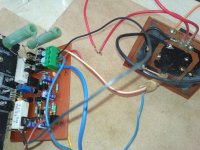
I make your AX-14 Amp today, during testing amp I got dc offset 40vdc and the same voltage on 0.33Ohm resister.I make all connection as you mention
Connect Input ground to PSU ground, a short input terminal, use 10 Ohm 10w resister instead of fuses. My supply voltage is +/-47Vdc.
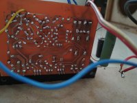
What are the problems? please see attached photo and help me.
Hello Apexsir
I make your AX-14 Amp today, during testing amp I got dc offset 40vdc and the same voltage on 0.33Ohm resister.I make all connection as you mention
Connect Input ground to PSU ground, a short input terminal, use 10 Ohm 10w resister instead of fuses. My supply voltage is +/-47Vdc.
What are the problems? please see attached photo and help me.
Attachments

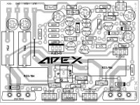
Which layout did you use? Check the diode orientation.
If I remember correctly, the original had wrong orientation which was later corrected. Check my layout and sch posted posted in this thread some time ago.
If I remember correctly, the original had wrong orientation which was later corrected. Check my layout and sch posted posted in this thread some time ago.
Dear prasi
I am using following layout . and I am get -40dc on sp out please help
I think you forget to connect signal ground from input to GND . See red line in attached picture. 🙂
Attachments
I think you forget to connect signal ground from input to GND . See red line in attached picture. 🙂
dear Alexmm sir
already connected Signal GND to PSU GND with wire, But still get -40Vdc on amp out.Whats wrong. please see the black wire in the picture
Attachments
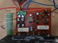
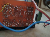
check if the track is proper...red circle
I have check track back again it's connected I have also checked in PCB layout and also not found any short track . I have also done light bulb test ,light glows only for fraction of time .
I have check track back again it's connected I have also checked in PCB layout and also not found any short track . I have also done light bulb test ,light glows only for fraction of time .
Did you check the output transistors for short circuit?
What you used for small signal transistors, are the pins correct connected,?
Ok..thank you sir,i will try to built tb1preamp.You can not use 50k for A2 preamp but you can use it with TB1 preamp.
regard
Voltage on R4=42.9 R6 and R7=-42.5 R14=-42.8Voltages on R4, R6, R7, R14 and R15?
R15=42.5
my rail voltage is +-45 v
wattaniyahi apex sir,
one channel ax14 finished,
supply voltage 50vdc, dc offset is 5.5mv,. no on off thumbs. thanks for the pcb.
one question, what is the ac output for clipping.?
Hello Wattaniya
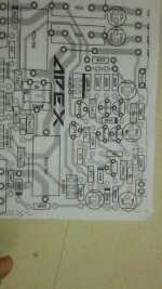
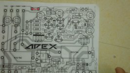
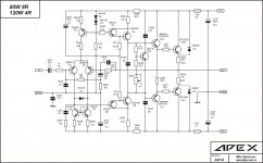
which schematics & PCB layout you used for your AX-14 Amp posted on Page 123 post #1221
Because I build one chanal for AX-14 amp from following schematics & PCB but, I am getting 40Vdc on Amp out during test dc offset, I already connected INput GND to PSU GND And short amp input, I check driver transistor also everything is ok. whats wrong, My rail voltage is +-45vDC.please help
Attachments

Last edited:
dear Alexmm sir
already connected Signal GND to PSU GND with wire, But still get -40Vdc on amp out.Whats wrong. please see the black wire in the picture[/QU
try to connect input gnd direct to psu
- Home
- Amplifiers
- Solid State
- 100W Ultimate Fidelity Amplifier