
First Apex Amp build for home
Hi Apex Sir and other friends,
I would like to build an Apex amp for my home use. I am looking for a design which can provide deep bass, wider sound stage and clean mid/highs. And the power requirement is between 100-200 watts. I have shortlisted the below models designed by Apex-
1. A33
2. A40
3. SR200
Could you please suggest one from the above list.
I would be using the PCB designed by Mr Alex MM.
I am so much excited in building my first Apex amp🙂.
Thank you Apex sir for being part of the diy community and for the great designs. And thanks to all diy enthusiasts.
Regards
Sha
Attachments

Last edited:
In stereo! 😀
too late to edit previous post, i/p cap orientation corrected...
Attachments
Use 300VA transformer with 2X35V AC, and U can use MJEs or TIPs in this case.
No 500W with MOSFETs in my projects.
Regards
I made this amplifier for test my home DIY speakers (two way TL).
D4 on component layout wrong polarity, in post #253 is correct component layout.
Hello Apexsir
Can I use +/-50Vdc 350VA Transformer for single chanal without any changes made in the circuit of your post #1, can it gives 100W on 8-ohm load.
And please give corrected PCB layout and, tips for testing of amp cold start(means before applying voltage) and hot start(after applying voltage).
Thanks
hi apex sir,
one channel ax14 finished,
supply voltage 50vdc, dc offset is 5.5mv. no on off thumbs. thanks for the PCB.
one question, what is the ac output for clipping.?
Hello Wataniya
which PCB layout you use for your Ax-14 amp, for +/-50dc can you change anything in the circuit or use as it is & which PSU circuit you use?
Can you shear your schematics, BOM for ax-14 & PSU you use, Because I have 50Vdc +/- with 350VA transformer and want correct schematics and PCB layout. my need is 100W on 8Ohm load.please help if you can
Thanks

Thank you sir..Let me see...
Regards,
Sumesh
Hello Wataniya
which PCB layout you use for your Ax-14 amp, for +/-50dc can you change anything in the circuit or use as it is & which PSU circuit you use?
Can you shear your schematics, BOM for ax-14 & PSU you use, Because I have 50Vdc +/- with 350VA transformer and want correct schematics and PCB layout. my need is 100W on 8Ohm load.please help if you can
Hello Wataniya
can you read my query please help.
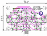
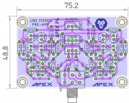
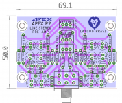
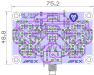
P4 Line Preamp
On similar lines (traces) as that of P2, here is P4🙂.
Attachments
Last edited:
Prasi,
can we get DIY pdf's, or Gerber files for these please.
Hello Rick,
Here you go🙂.
regards
Prasi
A note for those who want to etch their PCBs.
I have made the pdf's such a way that on a 4" x 6" copper clad, one can etch 4 PCBs at a time... Saves copper clad and etchant too...😀
But I would suggest to make use of cheap board houses, that way one could get double sided PCBs with gnd layer on top😉.
Attachments
Last edited:

Prasi, you are such a nice guy again with sorting the pcb layout.😀 I suppose this is for +-24 VDC, for working on +- 12VDC , which resistor values have to be decreased ?
Prasi, you are such a nice guy again with sorting the pcb layout.😀 I suppose this is for +-24 VDC, for working on +- 12VDC , which resistor values have to be decreased ?
For P2?
I am guessing R5 /R10 to 1k, based on the quick and dirty spice , here it is...
weird thing is I cant get it to work with Mr. Mile's original values. (I am no expert with spice BTW
 )
)Can some one confirm or check the spice sim?
there definately appears to be something wrong here, in spice sim...
Attachments
Last edited:
- Home
- Amplifiers
- Solid State
- 100W Ultimate Fidelity Amplifier