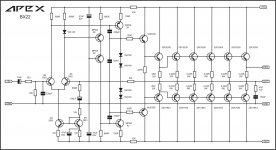
BX22
Three days ago, I modified AX11 using +-90VDC with cheap and easily to find transistors, almost like BX22. In simulation, I can achieved very high slew rate and low enough THD. I sent it to my social media friend (I never meet him before). He made PCB layout and test the prototype in almost 2 days only. He satisfied the result.
Actually, I made it for +-120VDC, but he made +-90VDC for class AB and will make +-120VDC for class H.
This topology is easy to scale up.
Post the modified ver.here🙂Three days ago, I modified AX11 using +-90VDC with cheap and easily to find transistors, almost like BX22. In simulation, I can achieved very high slew rate and low enough THD. I sent it to my social media friend (I never meet him before). He made PCB layout and test the prototype in almost 2 days only. He satisfied the result.
Actually, I made it for +-120VDC, but he made +-90VDC for class AB and will make +-120VDC for class H.
This topology is easy to scale up.
Last edited:
Three days ago, I modified AX11 using +-90VDC with cheap and easily to find transistors, almost like BX22. In simulation, I can achieved very high slew rate and low enough THD. I sent it to my social media friend (I never meet him before). He made PCB layout and test the prototype in almost 2 days only. He satisfied the result.
Actually, I made it for +-120VDC, but he made +-90VDC for class AB and will make +-120VDC for class H.
This topology is easy to scale up.
CCS in BX22 reduce voltage on CS transistor for about 30V (voltage drop on 10k)
Post the modified ver.here🙂
No, I can not.
The main different is I use Hawksford cascode on VAS and compensation is same as I use on my AX11 modification that built by Ivanlukic.
A33 sch
little question, resistor in offset trimer, right value is 470k or 470R?
little question, resistor in offset trimer, right value is 470k or 470R?
Right value is 470k.
Right value is 470k.
Thank you, this is valuable info, because on both boards here in forum - in silk is 470R, people can check it for itself 😉
Right value is 470k.
I updated the notes in the Directory thread to note this change.
Given the success of the FH9, I decided to take a totally fresh look at how to improve its performance and also to simplify its parts count. I think I have managed to do so, but it is so far removed from being an offshoot of one of Apex Audio's designs, I wonder if I should start a new thread or post here?
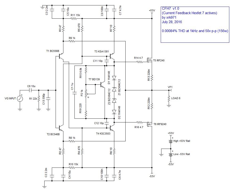
Basically it uses the venerable IRFP 240/9240 hexFET pair but in symmetric current feedback mode with a simple Vbe multiplier for temperature compensation. I have found that a simple resistor CCS is sufficient to achieve simulated THD of 0.00084% at 1kHz and 50v peak-peak on 53v rails. The simulated square wave performance is out of this world, clean and sharp up to 200kHz with no ringing. Oh, and did I mention that there are now only 7 active parts? Nothing exotic: BC546B/BC556B, KSA1381/KSC3503 VAS, BD139, and IRFP outputs... 🙂
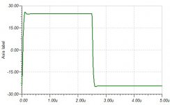
Here is a teaser square wave closeup at 200kHz:

If we kept it in this thread, I would probably call it the CFH7.
Basically it uses the venerable IRFP 240/9240 hexFET pair but in symmetric current feedback mode with a simple Vbe multiplier for temperature compensation. I have found that a simple resistor CCS is sufficient to achieve simulated THD of 0.00084% at 1kHz and 50v peak-peak on 53v rails. The simulated square wave performance is out of this world, clean and sharp up to 200kHz with no ringing. Oh, and did I mention that there are now only 7 active parts? Nothing exotic: BC546B/BC556B, KSA1381/KSC3503 VAS, BD139, and IRFP outputs... 🙂
Here is a teaser square wave closeup at 200kHz:
If we kept it in this thread, I would probably call it the CFH7.
Attachments
Last edited:
Hello xrk971
greetings nice to see you improving FH9 waiting for final schematic
warm regards
Andrew
greetings nice to see you improving FH9 waiting for final schematic
warm regards
Andrew
Given the success of the FH9, I decided to take a totally fresh look at how to improve its performance and also to simplify its parts count. I think I have managed to do so, but it is so far removed from being an offshoot of one of Apex Audio's designs, I wonder if I should start a new thread or post here?
Basically it uses the venerable IRFP 240/9240 hexFET pair but in symmetric current feedback mode with a simple Vbe multiplier for temperature compensation. I have found that a simple resistor CCS is sufficient to achieve simulated THD of 0.00084% at 1kHz and 50v peak-peak on 53v rails. The simulated square wave performance is out of this world, clean and sharp up to 200kHz with no ringing. Oh, and did I mention that there are now only 7 active parts? Nothing exotic: BC546B/BC556B, KSA1381/KSC3503 VAS, BD139, and IRFP outputs... 🙂
Here is a teaser square wave closeup at 200kHz:
If we kept it in this thread, I would probably call it the CFH7.
Is this similar to FX8CF
Attachments
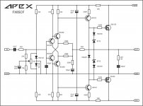
Is this similar to FX8CF
Hi Apex Audio:
A think it is a bit different as it has fewer stages. Ok, I will post here as there seems to be interest...
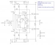
CFH7 - current feedback hexFET amp
Schematic:
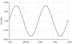
1kHz sine wave:

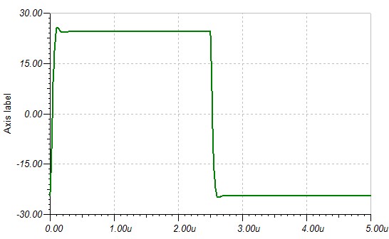
50kHz square wave:

200kHz square wave:
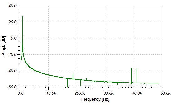
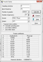
FFT spectrum at 1kHz:
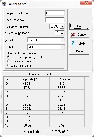
HD components at 1kHz:
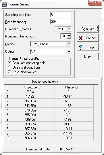
HD components at 20kHz:
Attachments
-
 CFH7-THD-Analysis-20kHz.jpg67.3 KB · Views: 9,371
 -
 CFH7-THD-Analysis.jpg66.7 KB · Views: 9,385
 -
 CFH7-FFT-1khz.jpg29.9 KB · Views: 9,417
 -
 CFH7-Oscope-200khz-square.jpg26.7 KB · Views: 9,578
 -
 CFH7-Oscope-50khz-square.jpg22 KB · Views: 9,560
 -
 CFH7-Oscope-1khz.jpg31.1 KB · Views: 9,669
 -
 CFH7-V1.0-SCHEMATIC.JPG95.1 KB · Views: 11,251
Hi Apex Audio:
A think it is a bit different as it has fewer stages. Ok, I will post here as there seems to be interest...
CFH7 - current feedback hexFET amp
Schematic:
1kHz sine wave:
50kHz square wave:
200kHz square wave:
FFT spectrum at 1kHz:
HD components at 1kHz:
HD components at 20kHz:
it seems vssa
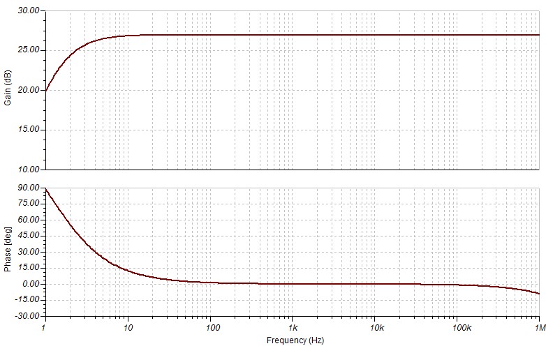
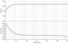
Excellent squarewaves. What about the phase and gain margin?
Here you go...
Attachments
it seems vssa
Certainly inspired by the last VSSA amp I built (Jason K thru-hole version), but I added a few tweaks here and there to allow use of hexFET and to give real clean square waves with high bandwidth and slew rate.
I tried 220R (the usual and customary value here) and it rings like crazy...
C grade then if you have it - my model was for B grade and seems ok.
C grade then if you have it - my model was for B grade and seems ok.
I tried 220R (the usual and customary value here) and it rings like crazy...
interesting
- Home
- Amplifiers
- Solid State
- 100W Ultimate Fidelity Amplifier