It just simulated 🙂
I built several amplifier base on simulation. Almost all of them can work at first built. It need some tweaking to make it perfect.
You can build another amplifier from me on my blog here. But, it use Indonesia languange.
thanks for the reply. Can you name the amplifier, you have so many.😱😀😀
Already a bit into making layout of AX11 as per you sch.
reg
prasi
Last edited:
Hi Sonal,
Very nice layout. Has it been tested by you or anyone? If so, what is the impression?
regards
Prasi
Hi Prasi, I have not tested I was very busy and my oscilloscope is broken because of lightning. I'll build it to see if it is working then ask Terry to to test further.
Regards,
Sonal
thanks for the reply. Can you name the amplifier, you have so many.😱😀😀
Already a bit into making layout of AX11 as per you sch.
reg
prasi
These have been built by my social media friends:
1. https://anistardi.wordpress.com/2015/02/19/elang-amplifier/
2. https://anistardi.wordpress.com/2015/02/17/tekukur-amplifier/
3. https://anistardi.wordpress.com/2014/12/31/symmetrical-ltp-vas/
4. https://anistardi.wordpress.com/2014/12/25/big-perkutut-amplifier/
5. https://anistardi.wordpress.com/2014/11/22/blameless-1200/
6. https://anistardi.wordpress.com/2014/10/14/perkutut-amplifier/
7. https://anistardi.wordpress.com/2014/04/19/aksa-55-dalam-simulasi/
Not all of my amplifier I designed to be 'best I can'. Some of them just use commonly and easy to find transistor at my country.
I improved Perkutut amplifier using Mr. Hugh Dean (AKSA) design philosophies but I can not share it because it is commercial.
If you have any question about it, you can PM me or make a new thread. I do not want to hijack this thread.
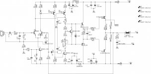
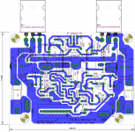
That's quite a lot of amps. 😀😱. Anyway, I have done a layout of the APEX AX-11 modified by you. Its your layout, but slightly modified to fit on-board coil and also protect pin (in case one wants to use apex protect)+ some other minor modifications. any comments by any members and you /Mr. Miles are welcome. Also attaching h/w the sch for info.
I will PM you regarding your amp.
regards
Prasi
P.S. Still I will be making some improvements in layout for aesthetics.
Attachments

Last edited:

Hi Prasi, I have not tested I was very busy and my oscilloscope is broken because of lightning. I'll build it to see if it is working then ask Terry to to test further.
Regards,
Sonal
Oh! Thats too bad regarding the oscilloscope. Well all the best for build and testing
reg
Prasi
That's quite a lot of amps. 😀😱. Anyway, I have done a layout of the APEX AX-11 modified by you. Its your layout, but slightly modified to fit on-board coil and also protect pin (in case one wants to use apex protect)+ some other minor modifications. any comments by any members and you /Mr. Miles are welcome. Also attaching h/w the sch for info.
I will PM you regarding your amp.
regards
Prasi
P.S. Still I will be making some improvements in layout for aesthetics.
C5 should be 4.7pF 🙂
Thanks for the catch. Here is the corrected and improved layout.C5 should be 4.7pF 🙂
reg
Prasi
Attachments

why attach a 15.8M pixel when a much smaller (1.1M pixel) would do?
Is this 59kB sch too small to read?
Does anyone prefer the 684kB sch?
😀😀. My software exports the sch in that format. I will have to download a good image compressor.
I was recommended to use Irfanview quite a few years ago by a couple of Members.
I am not good at learning new software, but can manage with this one.
It has enormous capabilities of which I only use a few.
I am not good at learning new software, but can manage with this one.
It has enormous capabilities of which I only use a few.
Hi Bimo and Mile,
For the schematic/layout posted in #5387, do any of the BD139/140 need to be on heat sink? I am planning to build a stereo version of this amp for a boom box project that was orginally intended to use Dayton D-class amp module, hence its better to have eagle eyes of experts to correct the layout before I pull the trigger. one small correction that I found is that the protect pin to be between emitter of 2SA1943 and its emitter resistor.
reg
Prasi
R14 might be a bit high.
You may have to reduce this to 910r, or 820r, or 750r, to get adequate output bias.
Q7 should monitor the Tj of all four output transistors and drivers.
I would prefer an LED instead of D1+D2.
You may have to reduce this to 910r, or 820r, or 750r, to get adequate output bias.
Q7 should monitor the Tj of all four output transistors and drivers.
I would prefer an LED instead of D1+D2.
Hi Bimo and Mile,
For the schematic/layout posted in #5387, do any of the BD139/140 need to be on heat sink? I am planning to build a stereo version of this amp for a boom box project that was orginally intended to use Dayton D-class amp module, hence its better to have eagle eyes of experts to correct the layout before I pull the trigger. one small correction that I found is that the protect pin to be between emitter of 2SA1943 and its emitter resistor.
reg
Prasi
The original design and layout was proven. Then I modified a little, but I like a small heatsink on BD139/140. Average power dissipation of BD139/140 still below 1W when use 3 Ohm load, it will safe at 25 degree Celsius room temperature.
R14 might be a bit high.
You may have to reduce this to 910r, or 820r, or 750r, to get adequate output bias.
Q7 should monitor the Tj of all four output transistors and drivers.
I would prefer an LED instead of D1+D2.
Thanks Andrew for the reply.
1. R14 can be and will be adjusted if necessary during testing.
2. Q7 will be mounted on main heat sink and is already at a convenient location.
3. D1+ D2 comb can be replaced with resistor 1k5 res and 3mm LED(red) ? Pl guide here with resistor values
regards
prasi
Thanks for the reply Bimo.The original design and layout was proven. Then I modified a little, but I like a small heatsink on BD139/140. Average power dissipation of BD139/140 still below 1W when use 3 Ohm load, it will safe at 25 degree Celsius room temperature.
I will rotate BD 139 BD140 (Q8,Q9) so that a small 1mm thick aluminium plate can be attached to the trannies.
regards
prasi
no resistor. Just a LED as voltage reference to the CCS..............
3. D1+ D2 comb can be replaced with resistor 1k5 res and 3mm LED(red) ? Pl guide here with resistor values
regards
prasi
no resistor. Just a LED as voltage reference to the CCS.
Like so?
regards
Prasi
PS:Correction on silk "replace D2 by led and D1 by jumper"
Attachments

Last edited:
Put in an extra pad to suit the 0.1" pin pitch of the LED.
That then allows other Builders to use either a LED+jumper, or two Diodes, or a LED+Diode.
The small advantage to using a LED+Diode is that they have opposite tempco.
That then allows other Builders to use either a LED+jumper, or two Diodes, or a LED+Diode.
The small advantage to using a LED+Diode is that they have opposite tempco.
Done!. Thanks.Put in an extra pad to suit the 0.1" pin pitch of the LED.
That then allows other Builders to use either a LED+jumper, or two Diodes, or a LED+Diode.
The small advantage to using a LED+Diode is that they have opposite tempco.
It would be good to have comments from Mr. Miles, who is the original designer of the circuit, on which the current version is based.
Attachments

Done!. Thanks.
It would be good to have comments from Mr. Miles, who is the original designer of the circuit, on which the current version is based.
If you use RED LED for CCS, please change R4 to 10K and R6 to 330. It make colector current of Q2 about 3mA.
- Home
- Amplifiers
- Solid State
- 100W Ultimate Fidelity Amplifier