
almost ready to rock... I have no so much time due Ice Hockey World Championship 😀😀😀
Nice work,
Regards
Mr. Mile,
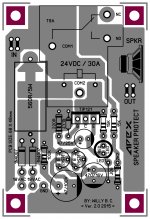
During some test I've done on this protect, when applied +/-DC on input.
The LED lit on but relay did not deactivate, (referring to the attached drawing) below are the parts used, the rest remain unchanged.
20R/5W
ZD 6V2/1W
2K2 - resistor used in series with LED to increase brightness.
Question: What's the changes needed to deactivate the relay when the LED lit on?
Regards,
Attachments
Mr. Mile,
During some test I've done on this protect, when applied +/-DC on input.
The LED lit on but relay did not deactivate, (referring to the attached drawing) below are the parts used, the rest remain unchanged.
20R/5W
ZD 6V2/1W
2K2 - resistor used in series with LED to increase brightness.
Question: What's the changes needed to deactivate the relay when the LED lit on?
Regards,
Can you measure voltages on TIP121...
Can you measure voltages on TIP121...
Im getting 1.26V - Base, 0.73V - Collector (relay engaged mode).
But when i applied DCVolts on input I'm getting 27V on collector and 0Volts on Base, the LED lit up but relay still engaged.
Last edited:
Im getting 1.26V - Base, 0.73V - Collector (relay engaged mode).
But when i applied DCVolts on input I'm getting 27V on collector and 0Volts on Base, the LED lit up but relay still engaged.
Voltages are OK, replace relay, it must go off with no voltage on coil.
Regards
must be the holding current of relay is low.. that is why the relay is still on via led/resistor.
V+ -----^^^^------^^^^----|>|---^^^^--- GND
..........20R/5w....... relay......led.....2k2
try to increase 2k2
V+ -----^^^^------^^^^----|>|---^^^^--- GND
..........20R/5w....... relay......led.....2k2
try to increase 2k2

Increasing 2k2 will slightly release the relay but its loosing the brighness of LED( too dimmed if i used the original value 15K).
Today i tried to install 1K5/1W resistor in parallel of relay coil, works perfect without loosing the LED brightness.
Thanks for the advise Mr. Mile.
Regards,
Today i tried to install 1K5/1W resistor in parallel of relay coil, works perfect without loosing the LED brightness.
Thanks for the advise Mr. Mile.
Regards,
Mr Mile
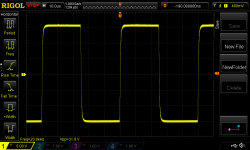
Just for fun I have soldered 22pF caps in A9 IPS, look what have You done 😀
Scale is 500ns (OPA2134 in it). It is really fast (i did not removed input filter for the measurement). Sounds fantastic.
Thanks
This is really confusing ! 😕
So many pages and I suddenly see A9 mentioned. What is it ? Power amp, Pre amp ? OPA2134 ....where ? Maybe the post number can be mentioned ? Cap, where, and how does it speed up things making something fantastic ?

Of course you can see that I am not reading this thread every day, post by post , hence the confusion ! 😉
Reference to some post where there is a circuit diagram ( of A9 ) would have been helpful !
Cheers.
This is really confusing ! 😕
So many pages and I suddenly see A9 mentioned. What is it ? Power amp, Pre amp ? OPA2134 ....where ? Maybe the post number can be mentioned ? Cap, where, and how does it speed up things making something fantastic ?
Of course you can see that I am not reading this thread every day, post by post , hence the confusion ! 😉
Reference to some post where there is a circuit diagram ( of A9 ) would have been helpful !
Cheers.
A9
Increasing 2k2 will slightly release the relay but its loosing the brighness of LED( too dimmed if i used the original value 15K).
Today i tried to install 1K5/1W resistor in parallel of relay coil, works perfect without loosing the LED brightness.
Thanks for the advise Mr. Mile.
Regards,
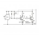
You can use this circuit for protect and ready leds.
Regards
Attachments
Mr Mile
Just for fun I have soldered 22pF caps in A9 IPS, look what have You done 😀
Scale is 500ns (OPA2134 in it). It is really fast (i did not removed input filter for the measurement). Sounds fantastic.
Thanks
A9 is my favorite CFA amplifier,
Regards
You can use this circuit for protect and ready leds.
Regards
Thanks Mr. Mile...
Can you suggest some parts value?
Thanks Mr. Mile...
Can you suggest some parts value?
Use BC546, Rb 10k and Rc 1k.
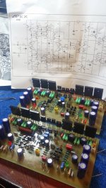
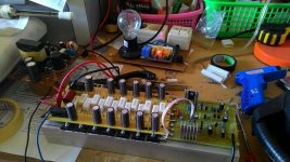
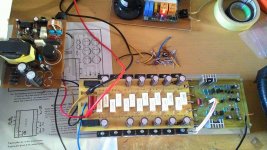
Still AX20 😀
still AX20 progress 😀 and only one channel 😱
with upgrade SMPS up to 350watt
i try to set 20mV on R emitor (i'm used 0.33R), why final transistors so hot,
now only run at 10-15mV it's enough but still not satisfied 😀
still AX20 progress 😀 and only one channel 😱
with upgrade SMPS up to 350watt
i try to set 20mV on R emitor (i'm used 0.33R), why final transistors so hot,
now only run at 10-15mV it's enough but still not satisfied 😀
Attachments
20mV of Vre biasing gives 60mA of bias current through each output pair.
It looks like you have a 6pr output stage plus a pair of drivers.
If your supply voltage is +-10Vdc then your output stage has to dissipate ~8.5W per 10Vsupply
a +-50Vdc supply will result in >42W of heat in your output stage. That will be HOT, before you start playing any music.
It looks like you have a 6pr output stage plus a pair of drivers.
If your supply voltage is +-10Vdc then your output stage has to dissipate ~8.5W per 10Vsupply
a +-50Vdc supply will result in >42W of heat in your output stage. That will be HOT, before you start playing any music.
20mV of Vre biasing gives 60mA of bias current through each output pair.
It looks like you have a 6pr output stage plus a pair of drivers.
If your supply voltage is +-10Vdc then your output stage has to dissipate ~8.5W per 10Vsupply
a +-50Vdc supply will result in >42W of heat in your output stage. That will be HOT, before you start playing any music.
Thanks Mr Andrew to explain it,
that means total rms out of power will loss due to dissipate ~8.5W per 10V supply, is'n it?
i'm used 80Vdc (+-40Vdc) of supply and load will use max 4 ohm,
how many watt will produce this Ax?
- Home
- Amplifiers
- Solid State
- 100W Ultimate Fidelity Amplifier