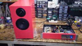

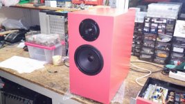

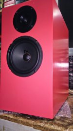
photos
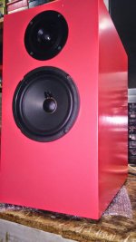
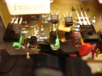
could you post pictures with higher resolution? great job you did here but it can not be seen as it should be...
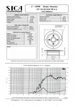
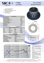
those loudspeakers are also APEX TQWP? what drivers were used?


hello mister Mile
I have a question I was simulating with multism 13 and I notice that I can get even more power if I change only one value resistor from 47 to 33 ohms is that be ok to do ? I notice that I can get more power output and THD still good and low, at 1KHz and 1Vp sine wave @4 ohms load I get about 240W using 70V rails with 4 pairs and with same setting @8 ohms I get about 120W I mean I'm not pushing hard the simulations to it's clipping area, 😀 just let me know is that 45R resistor can be change or not, when you get time of course 🙂
Regards
Juan
You can not get more power with change resistor value from 47 to 33 ohms, you only get more gain (more sensitivity). Power is same with +/-70V only you need more input voltage to go on cliping level.
Regards
Nice work, what about sound?
Regards
Deep bass soft mids, the tremble is 3~4 db up. Tomorrow i will fix this in crossover ..
You can not get more power with change resistor value from 47 to 33 ohms, you only get more gain (more sensitivity). Power is same with +/-70V only you need more input voltage to go on cliping level.
Regards
ok roger that, so I will keep original value 47 🙂
Regards
Juan
Deep bass soft mids, the tremble is 3~4 db up. Tomorrow i will fix this in crossover ..
Can you post your crossover circuit, atenuate treble with resistors is easy.
Regards
Can you post your crossover circuit, atenuate treble with resistors is easy.
Regards
Hello Apex, I use this formula for attenuation
L pad calculator - attenuation dB damping impedance decibel loudspeaker speaker voltage divider - sengpielaudio Sengpiel Berlin
best regards , Dimitris🙂
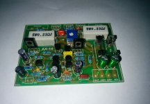
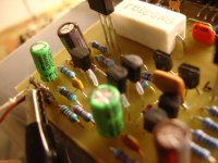
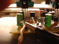
Don't use these 2n5401 transistors!My new AX-14
I see using here a970,amplifier is more musican.
In VAS stage i use ksa1381,ksc3503.
Pay attention for wrong pin placement only!
Attachments

Last edited:
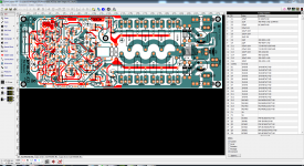
Hello guys I still working on the A33 project and have made my mind I will order a small batch for myself " I will personally make a risk of my own, I rather have an error on me than share the file and some one have the error " so I will continue checking the layout there is no hurry on doing this re-checks over and over I will take my time on doing this, so far I just tweak it a little bit, and I'm identified ever single part that is on the layout to make sure is correct, as you can see on the Sprint Layout image, also there is not changes on the original schematic I'm fallowing the original schematic as it is, the only difference is that it will have 2 more pairs, and the adding of MUR460 diodes and some other components 🙂 same procedure I did to the AX-14T basically 😛
yes this time I write a little bit more jejejejeje 😀
here is the video of my studies
https://www.youtube.com/watch?v=v5Wc0sGyLrQ&list=UUEV_-UcnVM-o3KnQe6nemTQ
Regards
Juan
yes this time I write a little bit more jejejejeje 😀
here is the video of my studies
https://www.youtube.com/watch?v=v5Wc0sGyLrQ&list=UUEV_-UcnVM-o3KnQe6nemTQ
Regards
Juan
Attachments

Last edited:
- Home
- Amplifiers
- Solid State
- 100W Ultimate Fidelity Amplifier