Now seal the fan to the heatsink so that all the air passing through the fan also passes along the heatsink to the far end.......... 😎..............
This amp will be used in the school that I was there long time ago.
I build it for my teacher there in the school & He and all the students there must be like the sound 🙂 ........
So I adjust the bias, the 1k resistor must be increased.
Regards
hi john.. how much value did you use for 1k? and how much bias did you set for your AX20?
thanks..
Last edited:
Sip thanks Mas Reski, ditunggu AX-nya sampean 🙂Great job Bli...
I'm waiting your AX-series build
Hi Thimios, do you gonna build this one too?Hi John and happy new year to all of us
Is this pcb for sharing?
Best regards.
Thimios.
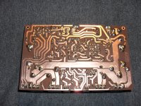
This PCB have some error (the electrolyte need bigger room 😀)
but working fine,
if you want I will send you the file.
Dear AndrewT, Thanks for your suggestion.Now seal the fan to the heatsink so that all the air passing through the fan also passes along the heatsink to the far end.
When closed, the case & heatsink + 2 fans already form good air flow so the temperature is very stable. I've run it more than 12 hours a day (but not so loud)
Hi Dacz,hi john.. how much value did you use for 1k? and how much bias did you set for your AX20?
thanks..
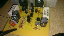
I add 470ohm resistor in series with 1k, take a better look at the picture 🙂
you can see a resistor mounted off-board
With 1k I can't set the bias.
With 1k470 I can easily set bias to 14mV on 0R33 resistor
(bias at 10mV on 0R33 is enough).
but I can't measure DC offset because it is zero 😀
Regards
Last edited:
if your meter can consistently read 10mVdc and 14mVdc, then it should be able to read 1 to 2 mVdc of output offset.
I don't believe your offset is always less than 0.05mVdc. This is what a 0.0 reading on a 199.9mVdc scale means.
I don't believe your offset is always less than 0.05mVdc. This is what a 0.0 reading on a 199.9mVdc scale means.
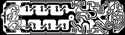
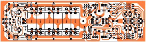
I share it & please comment for the layout
I set the meter to 200mV & the DC offset is 0.00 on one channel and 1mV max on other channel. I think I'm very lucky 🙂
(I only match the 2N5401 & glued together)
VAS use BC550B-560B(not matced) MJE340-350 (close hFE)
driver KSE340-KSE350 2SA1837-2SC4793 (not matced)
I think someday I will made it again with zero offset & with the picture to proof it 😎
Kudos for the designer 🙂
So here the files for anyone that one to build it...
(It is symmetrical look layout)
PCB size is 50mm * 175mm
& in the .zip there is .DIP file that can be opened with Diptrace
Regards
I also not believe it at first time, I was build AX-14 with 7-8mV DC offset.if your meter can consistently read 10mVdc and 14mVdc, then it should be able to read 1 to 2 mVdc of output offset.
I don't believe your offset is always less than 0.05mVdc. This is what a 0.0 reading on a 199.9mVdc scale means.
I set the meter to 200mV & the DC offset is 0.00 on one channel and 1mV max on other channel. I think I'm very lucky 🙂
(I only match the 2N5401 & glued together)
VAS use BC550B-560B(not matced) MJE340-350 (close hFE)
driver KSE340-KSE350 2SA1837-2SC4793 (not matced)
I think someday I will made it again with zero offset & with the picture to proof it 😎
Kudos for the designer 🙂
So here the files for anyone that one to build it...
(It is symmetrical look layout)
PCB size is 50mm * 175mm
& in the .zip there is .DIP file that can be opened with Diptrace
Regards
Attachments
Last edited:
I also not believe it at first time, I was build AX-14 with 7-8mV DC offset.
I set the meter to 200mV & the DC offset is 0.00 on one channel and 1mV max on other channel. I think I'm very lucky 🙂
(I only match the 2N5401 & glued together)
VAS use BC550B-560B(not matced) MJE340-350 (close hFE)
driver KSE340-KSE350 2SA1837-2SC4793 (not matced)
I think someday I will made it again with zero offset & with the picture to proof it 😎
Kudos for the designer 🙂
So here the files for anyone that one to build it...
(It is symmetrical look layout)
PCB size is 50mm * 175mm
& in the .zip there is .DIP file that can be opened with Diptrace
Regards
Nice PCB,
Regards
You have confused me again.......I set the meter to 200mV & the DC offset is 0.00 on one channel and 1mV max on other channel........
200.0mVdc or 2000mVdc?
or is it 199.9mVdc or 1999mVdc?
Is you instrument a 2000 count device, or a 20000 count device.
1mVdc and 0.00mVdc seems to be from different instruments? What is the resolution of the scale you have set to?
Last edited:
ThanksNice PCB,
Regards
Oops, I'm sorry I have miss-type that...You have confused me again.
200.0mVdc or 2000mVdc?
or is it 199.9mVdc or 1999mVdc?
Is you instrument a 2000 count device, or a 20000 count device.
1mVdc and 0.00mVdc seems to be from different instruments? What is the resolution of the scale you have set to?
 or I saw it from the back😀
(I wish I have 0.00mV measuring device)
00.0
that is on the meter
but too bad the amp is not here anymore
and I will guarantee that the 0.0mVdc does not hold constant over a range of operating temperatures, nor from cold start up, through warm up, to fully hot after a period of loud music.
Hi bli john punapi gatra? (how are u?)
thanks for sharing yours symmetric layout version with 3 tr final,
i hope, i can finis my layout with TO3 tr final (only build one for fun J), and try your version 😀
and i will take your time for many question 😀

BR//
Madde
thanks for sharing yours symmetric layout version with 3 tr final,
i hope, i can finis my layout with TO3 tr final (only build one for fun J), and try your version 😀
and i will take your time for many question 😀
BR//
Madde
Hi Made, so it is you 😀
(your fb's name is different, code S.M.S)
just change the OP's to TO-3 & you will have a robust + symmetrical look 😀
I'm waiting your build here 🙂
you can't post here if you find any trouble,
all parts you can buy it in Bali that is the good news
I will help you as I can 🙂
Regards
(your fb's name is different, code S.M.S)
just change the OP's to TO-3 & you will have a robust + symmetrical look 😀
I'm waiting your build here 🙂
you can't post here if you find any trouble,
all parts you can buy it in Bali that is the good news
I will help you as I can 🙂
Regards

Add protect & clip indicator on blank space 🙂
(Or big electrolyte's bank there)
Also move base resistor(R-B) & emitter resistor(R-E) close to the transistors.
BD139 still in middle & 2SA-SC you can move them so the TO-3 have same space
You can mount R-B & R-E in bottom place if that help
(Or big electrolyte's bank there)
Also move base resistor(R-B) & emitter resistor(R-E) close to the transistors.
BD139 still in middle & 2SA-SC you can move them so the TO-3 have same space
You can mount R-B & R-E in bottom place if that help
Apex AX20
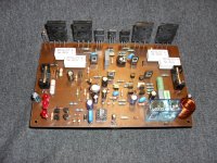
Hi mr Mile, first of all happy new year for you and keep healthy with your electronic personal set 🙂. So, here is my second channel AX 20 tested, sounds great, next step, the box. Once more thanks a lot Mile.
Regards
Hi mr Mile, first of all happy new year for you and keep healthy with your electronic personal set 🙂. So, here is my second channel AX 20 tested, sounds great, next step, the box. Once more thanks a lot Mile.
Regards
Attachments
http://www.diyaudio.com/forums/solid-state/164093-100w-ultimate-fidelity-amplifier-221.html#post3502644
Pivot the to-3 devices...check out willy's layout...very compact.
Pivot the to-3 devices...check out willy's layout...very compact.
Hi mr Mile, first of all happy new year for you and keep healthy with your electronic personal set 🙂. So, here is my second channel AX 20 tested, sounds great, next step, the box. Once more thanks a lot Mile.
Regards
Nice work.
Regards
Hi !
Can I use his design http://www.diyaudio.com/forums/soli...imate-fidelity-amplifier-221.html#post3502644
to make a pcb and start the build ?
Is this PCB design copyrighted ?
Can I use his design http://www.diyaudio.com/forums/soli...imate-fidelity-amplifier-221.html#post3502644
to make a pcb and start the build ?
Is this PCB design copyrighted ?
hi mr. apex,
can i use +/-60v rail to my ax20 (2 pairs)
somewhere down this thread, it was posted that the suggested max rails for 2 pairs is +/-60v. i just can't recall the post#.
🙂
- Home
- Amplifiers
- Solid State
- 100W Ultimate Fidelity Amplifier