tests
Ansolder output transistors and check with ohmmeter.
Can someone guide me where to measure and how much the expected volatge?
Ansolder output transistors and check with ohmmeter.
Last edited:
Ansolder output transistors and check with ohmmeter.
slowly ...maybe not yet
not that I have better suggestion

could it be a reversed diode ?
AX11 under....test!
in continua of ax11 testing i must mention that
In rail voltage +/-22v output is biasing in zero.(0mv on emmiter resistors 0.22R)Because of trimmer absence there isn't possibility of regulating.
In rail voltage +/-42v output is biasing in zero.(0mv on emmiters resistors 0.22R. the same.
Changing 4k7standar resistor in base of mpsa13 with a trimmer is possible to regulate current but this (current) is absolutely anstable.When power on device current continually increase,even although it had previously been set correctly.
This isn't happens at rail voltage +/-22v ,so i beleive this can't work at +/- 42v.
I tryed to change small transistors bc 640 &bc639 with stronger MJE340 MJE350 and ingreacing heatsring but without results.
Finally some measurments .
12.5w RMS /8R/1V RMS INPUT
25W RMS/4R /1V RMS INPUT.
78WRMS/8R/2.5V RMS INPUT
156WRMS/4R/2.5V RMS INPUT
Starting to clip symetrical at 2.8vrms input.
All measurments at 2.5KHz sinusoidal waveforms.
Thats fo now.
It is very interesting if we have Apex opinion.
Set bias after 20 min runing amp whan VAS transistors are hot, and reset after 10 min whan output transistors are warm.
in continua of ax11 testing i must mention that
In rail voltage +/-22v output is biasing in zero.(0mv on emmiter resistors 0.22R)Because of trimmer absence there isn't possibility of regulating.
In rail voltage +/-42v output is biasing in zero.(0mv on emmiters resistors 0.22R. the same.
Changing 4k7standar resistor in base of mpsa13 with a trimmer is possible to regulate current but this (current) is absolutely anstable.When power on device current continually increase,even although it had previously been set correctly.
This isn't happens at rail voltage +/-22v ,so i beleive this can't work at +/- 42v.
I tryed to change small transistors bc 640 &bc639 with stronger MJE340 MJE350 and ingreacing heatsring but without results.
Finally some measurments .
12.5w RMS /8R/1V RMS INPUT
25W RMS/4R /1V RMS INPUT.
78WRMS/8R/2.5V RMS INPUT
156WRMS/4R/2.5V RMS INPUT
Starting to clip symetrical at 2.8vrms input.
All measurments at 2.5KHz sinusoidal waveforms.
Thats fo now.
It is very interesting if we have Apex opinion.
Attachments
Last edited:
in continua of ax11 testing i must mention that
In rail voltage +/-22v output is biasing in zero.(0mv on emmiter resistors 0.22R)Because of trimmer absence there isn't possibility of regulating.
In rail voltage +/-42v output is biasing in zero.(0mv on emmiters resistors 0.22R. the same.
Changing 4k7standar resistor in base of mpsa13 with a trimmer is possible to regulate current but this (current) is absolutely anstable.When power on device current continually increase,even although it had previously been set correctly.
This isn't happens at rail voltage +/-22v ,so i beleive this can't work at +/- 42v.
I tryed to change small transistors bc 640 &bc639 with stronger MJE340 MJE350 and ingreacing heatsring but without results.
Finally some measurments .
12.5w RMS /8R/1V RMS INPUT
25W RMS/4R /1V RMS INPUT.
78WRMS/8R/2.5V RMS INPUT
156WRMS/4R/2.5V RMS INPUT
Starting to clip symetrical at 2.8vrms input.
All measurments at 2.5KHz sinusoidal waveforms.
Thats fo now.
It is very interesting if we have Apex opinion.
Looks like MPSA13 not work as Vbe multiplayer, what is emmiter-colector voltage measurements on MPSA13 ?
slowly ...maybe not yet
not that I have better suggestion
could it be a reversed diode ?
100% sure the diode is at correct orientation. I'll post the picture when my internet connection becomes good.
I will consider unsoldering the output trans for fault checking.
check if you might have powered up amp with bias pot in the wrong opposite position
or else, why would they fail ?
or else, why would they fail ?
AX11 under....test!
Hi Mr .
I haven't use MPSA13 .Instead of this i use 2n6427.Vec=3.2v
Thanks for replay!
Looks like MPSA13 not work as Vbe multiplayer, what is emmiter-colector voltage measurements on MPSA13 ?
Hi Mr .
I haven't use MPSA13 .Instead of this i use 2n6427.Vec=3.2v
Thanks for replay!
AX11 under....test!
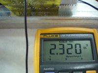
Can't delete previous message Vec=2.3v (2N6427)Hi Mr .
I haven't use MPSA13 .Instead of this i use 2n6427.Vec=2.3v
Thanks for replay!
Attachments
Last edited:
Can't delete previous message Vec=2.3v (2N6427)
Ok, Vec must drop under 2V on warm amp.
AX11 under....test!
i had repeated tests with +/-35v and i believe everything is ok at this rail voltage.Instead of 4k7 base resistor at 2N6427 i put 3k3 in series with 47R (as measured trimmer in previus test).
Current remained absolutly stable after 3 hours of continuas running.
Testing vbe multiplayer by placement solder iron on it ,show instant current drop so that is ok.
Maybe i repeat trimmer setting and set voltage 15 mv on 0.22r tomorrow
Another time ..your opinion Mr Apex.Is +/-35v the max power supply for this unit?
I have another question.
What you say for Mat02 instead of bc546 as input stage?
Is it direct replacement without others changes?
Thanks for all.
Best regards!
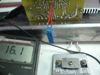
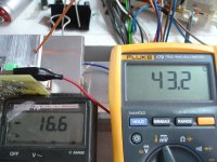
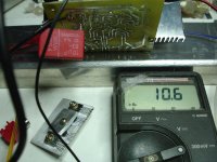
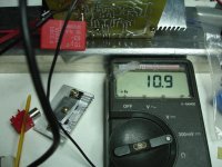
Photos shows current at start of test and at the end of tests after 3 hours.
Ok, Vec must drop under 2V on warm amp.
i had repeated tests with +/-35v and i believe everything is ok at this rail voltage.Instead of 4k7 base resistor at 2N6427 i put 3k3 in series with 47R (as measured trimmer in previus test).
Current remained absolutly stable after 3 hours of continuas running.
Testing vbe multiplayer by placement solder iron on it ,show instant current drop so that is ok.
Maybe i repeat trimmer setting and set voltage 15 mv on 0.22r tomorrow
Another time ..your opinion Mr Apex.Is +/-35v the max power supply for this unit?
I have another question.
What you say for Mat02 instead of bc546 as input stage?
Is it direct replacement without others changes?
Thanks for all.
Best regards!
Photos shows current at start of test and at the end of tests after 3 hours.
Attachments
Last edited:
100% sure the diode is at correct orientation. I'll post the picture when my internet connection becomes good.
I will consider unsoldering the output trans for fault checking.
Attachments
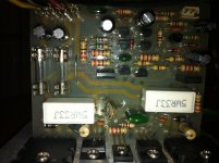
Picture can't show faliture, post voltage measurements on resistors, transistors and diodes.
Ok I'll take some measurements tonight.
AX11 under....test!
waiting Apex answers🙂i had repeated tests with +/-35v and i believe everything is ok at this rail voltage.Instead of 4k7 base resistor at 2N6427 i put 3k3 in series with 47R (as measured trimmer in previus test).
Current remained absolutly stable after 3 hours of continuas running.
Testing vbe multiplayer by placement solder iron on it ,show instant current drop so that is ok.
Maybe i repeat trimmer setting and set voltage 15 mv on 0.22r tomorrow
Another time ..your opinion Mr Apex.Is +/-35v the max power supply for this unit?
I have another question.
What you say for Mat02 instead of bc546 as input stage?
Is it direct replacement without others changes?
Thanks for all.
Best regards!
Photos shows current at start of test and at the end of tests after 3 hours.
waiting Apex answers🙂
+/-35V is suggested rail voltage for AX11, if you can't find it stable on higer voltage keep this as maximum.
AX11 under....test!
Coming soon more datails on youtube!
Full measurments and AX11 IN ACTION after bias stabilize.
Thanks again Mr Apex.
regards.
+/-35V is suggested rail voltage for AX11, if you can't find it stable on higer voltage keep this as maximum.
Coming soon more datails on youtube!
Full measurments and AX11 IN ACTION after bias stabilize.
Thanks again Mr Apex.
regards.
I built AX-14, but I got 49VDC offset!!?? What is wrong or what could be the parts that are defective? 😕😕😕
Input GND is already connected to PSU GND.
Bro... Consider also to double check pin orientation of MJE's 340/350 by meter, be sure you inserted correctly, this is one of the case if you have huge offset when inserted inverted pins one of your pre-drivers.
It happens to me in middle east MJE340 by ON semiconductor as per datasheet pins are ECB but in actual check by meter it’s BCE.
Good luck...
Regards,
AX11 under....test!
Pushing AX11 to the limits.
Take a look here.AX11 pushing ax11 at the limits - YouTube
Coming soon more datails on youtube!
Full measurments and AX11 IN ACTION after bias stabilize.
Thanks again Mr Apex.
regards.
Pushing AX11 to the limits.
Take a look here.AX11 pushing ax11 at the limits - YouTube
Last edited:
- Home
- Amplifiers
- Solid State
- 100W Ultimate Fidelity Amplifier