AX11 under....test!
Exactly as your shematic or maybe by other transistors but this is a weekend amplifier in any case .With that I had and a home made pcb...waiting parts for sr200.
Best regards.
Mr mile that is one of my next steps!Nice you can fix VAS transistor to heatsink for better cooling like this:
Exactly as your shematic or maybe by other transistors but this is a weekend amplifier in any case .With that I had and a home made pcb...waiting parts for sr200.
Best regards.
Last edited:
400W/4R[/
Thats nice.....
Waiting your updated schematic..
Thanks...
Last edited:
AX11 under....test!
Supose you confused.
If we say for Apex AX11 NOT HX11 rail voltage as Mr apex sai is +/-25 min to +/-50max.
In my AX11 i start to test it from +/-12v next to +/- 15v and finall to +/- 22v.It is the limit of my power supply.
Now i think is safe to operate AX11 with +/- 42v and test it again.
HX11 is another amplifier .
suggestion how to do that power supply ?
35+35V main trafo, and adding a 12+12V or 15+15V trafo ?
Supose you confused.
If we say for Apex AX11 NOT HX11 rail voltage as Mr apex sai is +/-25 min to +/-50max.
In my AX11 i start to test it from +/-12v next to +/- 15v and finall to +/- 22v.It is the limit of my power supply.
Now i think is safe to operate AX11 with +/- 42v and test it again.
HX11 is another amplifier .
Supose you confused.
ah, test voltages only
thanks for explaining
HX11 test with +/-50,+/-70V rail voltage, output clip level is 40V RMS (400W at 4R)
HX11 Test - YouTube
AX11 under....test!
Hi Mr Apex.
I think the increased supply voltage would have the effect of increasing the quiescent current but this did not happen.
With rail voltage +/-42v CURRENT is MINIMUM ,continues to be unmeasurable on 0.22r.
Where can we put a trimer on the attached shematics
?
Finally is my probleme because of the replecements parts?
Hi Mr.
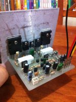
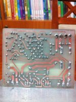
As i promise the AX11 is here today🙂
bf 872 instade of mpsa92 diferent base
2n6427 instade of mpsa13 same base
2sa1943
2sc5200 final out
Tested rail voltage +/- 23v from two stabilized power supplies
Thats for now ....coming soon on youtube!
For listening of cource.
Thanks Mr Apex.
Pai attention ..in first two photos bd139 and bd140 wrong position!

Hi Mr Apex.
I think the increased supply voltage would have the effect of increasing the quiescent current but this did not happen.
With rail voltage +/-42v CURRENT is MINIMUM ,continues to be unmeasurable on 0.22r.
Where can we put a trimer on the attached shematics
?
Finally is my probleme because of the replecements parts?
Attachments
Last edited:
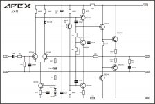
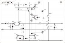
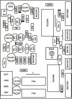
The left diagram shows the bias voltage trimmer.
The right diagram has the trimmer on the wrong side of the transistor.
The right diagram has the trimmer on the wrong side of the transistor.
AX11 under....test!
This maybe more efficiency
trimmer 2k2
Let's wait for Apex opinion.
The left diagram shows the bias voltage trimmer.
The right diagram has the trimmer on the wrong side of the transistor.
This maybe more efficiency
trimmer 2k2
Let's wait for Apex opinion.
Attachments
Last edited:
Max bias voltage will be ~ Vbe * {1+3k3/2k2} ~ 2.5Vbe
But you have 4Vbe in the output stage.
Measure the bias voltage as you change the trimmer.
Measure the Vdrop of that 220r as you change the trimmer.
Now do you understand why the output bias is near zero and appears not to change?
But you have 4Vbe in the output stage.
Measure the bias voltage as you change the trimmer.
Measure the Vdrop of that 220r as you change the trimmer.
Now do you understand why the output bias is near zero and appears not to change?
Max bias voltage will be ~ Vbe * {1+3k3/2k2} ~ 2.5Vbe
But you have 4Vbe in the output stage.
Measure the bias voltage as you change the trimmer.
Measure the Vdrop of that 220r as you change the trimmer.
Now do you understand why the output bias is near zero and appears not to change?
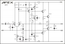
Placing a trimmer 10k in place of 4k7 resistor of original shematic idle curent is controled and easy setting to 33mv on 0.22r emitter resistor but in this case idle current isn't stable and continuas rice .Vas transistors come very hot because of no temperature monitor by the current source?
AX11 under....test!
it's mine wrong mr apex say +/-15mv on 0.22r
lets try it this afternoon.
Use trimer and set about 15mV on 0.33R/5W
it's mine wrong mr apex say +/-15mv on 0.22r
lets try it this afternoon.
Last edited:
it's mine wrong mr apex say +/-15mv on 0.22r
lets try it this afternoon.
Set bias after 20 min runing amp whan VAS transistors are hot, and reset after 10 min whan output transistors are warm.
Set bias after 20 min runing amp whan VAS transistors are hot, and reset after 10 min whan output transistors are warm.
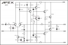
ok Mr Apex but how can set bias in the original shematic?
Finally is this modification the right way?
Attachments
I built AX-14, but I got 49VDC offset!!?? What is wrong or what could be the parts that are defective? 😕😕😕
Input GND is already connected to PSU GND.
Input GND is already connected to PSU GND.
Attachments
diode in4007 is correct?
diode placement is correct base on the component layout.
its look like the dry joint connection of 2sc4793 pin
sorry for my bad english
lightly soldered but contact is good.
I built AX-14, but I got 49VDC offset!!?? What is wrong or what could be the parts that are defective? 😕😕😕
Input GND is already connected to PSU GND.
Can someone guide me where to measure and how much the expected volatge?
Input GND is already connected to PSU GND.
SG(signal ground) ?
I suppose its already connected to ground directly on the board, and should only connect to input signal wires shield/connector
but could still sound like you might have a missing connection(ground ?) somewhere
- Home
- Amplifiers
- Solid State
- 100W Ultimate Fidelity Amplifier