I build SR200 and B500 both of them is fine,good quality,but when I build ax14, I got in trouble the first time,
please heklp me
please heklp me
Mr, Mike ax14 I've completed three times, but I have a problem, when I turned, shouted directly ax14 mixed humm.please help me.
ax14 mine exactly with this picture.
Post pictures with wireing, remove 100nF from input GND to power GND.
Thanks for help, today I replaced resistor to 1k5 but still same problem. I'll like to know voltage between collector-emitter of BD139(Amp has 1.5V), Other amp NX-14 which I have build previously have 6.7V at collector-emitter of BD139.Nice work, replace 1k resistor (base-colector BD139) with 1k5 and you can set bias.
Regards

Thanks for help, today I replaced resistor to 1k5 but still same problem. I'll like to know voltage between collector-emitter of BD139(Amp has 1.5V), Other amp NX-14 which I have build previously have 6.7V at collector-emitter of BD139.
Voltage between collector-emitter of BD139 must be about 2,2V
Hi Apex, I want to make AX14 driver TEF scheme like this, is there any scheme is correct?
thanks

thanks

thanks for the super fast response, but I want to make power with 6-pair transistor finals, so i separate driver circuit with transistor circuit finals. is there any wrong track with my PCB schematic? i'm sorry my with english
regards
regards
thanks for the super fast response, but I want to make power with 6-pair transistor finals, so i separate driver circuit with transistor circuit finals. is there any wrong track with my PCB schematic? i'm sorry my with english
regards
Wrong track...
Attachments
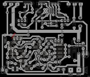
thank you for the correction, and this picture after my revision, and I hope this is true ...

nice board really!
Glad to read this!
Amplifier is running. I made the complete wiring (PSU, Amp...) new and had to changed R16 from 1k to 1k5 to adjust the bias. Layout seems to be correct.
regards Olaf
Glad to read this!
Uh Oh!
So the 2 fuses blew on one of the boards. Replaced and started poking around with the multimeter and now I have 12.6V on BOTH outputs!!!
The output transistors all seem to test fine - could the inputs be blown now?
Not sure what caused the fault but the bias seems to adjust properly on both channels...
The 12.6V is on BOTH the input and the output...
UGH!
Uh Oh!
So the 2 fuses blew on one of the boards. Replaced and started poking around with the multimeter and now I have 12.6V on BOTH outputs!!!
The output transistors all seem to test fine - could the inputs be blown now?
Not sure what caused the fault but the bias seems to adjust properly on both channels...
The 12.6V is on BOTH the input and the output...
UGH!
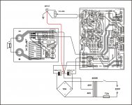
Do you connect GND from PSU to amp input (red line)?
Attachments
OK I wired up as prescribed and I have really bad hummmm
Offset is good less than 10mV, bias is 70mV on 0.22 resistor, voltage is 40v.
Offset is good less than 10mV, bias is 70mV on 0.22 resistor, voltage is 40v.
All right...I disconnected the input ground wire to the PSU ground but kept the input ground to star ground. Another wire from input ground to PCB input ground.
Now the amp again is very silent.
I had a bad trace on the mje15031 and was not getting a signal...
I am glad to report back that bias, humm, and sound are all back under control.
Now the amp again is very silent.
I had a bad trace on the mje15031 and was not getting a signal...
I am glad to report back that bias, humm, and sound are all back under control.
All right...I disconnected the input ground wire to the PSU ground but kept the input ground to star ground. Another wire from input ground to PCB input ground.
Now the amp again is very silent.
I had a bad trace on the mje15031 and was not getting a signal...
I am glad to report back that bias, humm, and sound are all back under control.
OK, can you post pictures?
Regards
hello vostro,,my ax14 still like the time, I use your wiring but the result is still the same, and I do take advice from Mr.Mile to 100nF leading to gnd.the result still the same, ax14 shouts mixed humm but works.please help me vostro
try only running input ground to chassis star ground and to PCB ground.
It helped with my setup and DC offset is less than 10mV.
Board ground and speaker ground go to PSU "ground" point.
! wire goes from PSU ground point to chassis star ground and earth ground from power inlet goes to chassis ground.
No hummm/buzz anymore.
It helped with my setup and DC offset is less than 10mV.
Board ground and speaker ground go to PSU "ground" point.
! wire goes from PSU ground point to chassis star ground and earth ground from power inlet goes to chassis ground.
No hummm/buzz anymore.
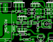
Mr. Mile,
This gonna be my next project to follow, please let me know if you found an error.
Thanks...
Regards,
Hi Cerna,
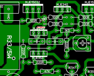
I noticed there was an error on the PCB track that you created in post 1798, this I include the correction
Regards Denmas😉
Attachments
- Home
- Amplifiers
- Solid State
- 100W Ultimate Fidelity Amplifier