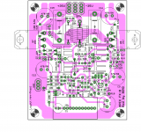
Thanks Astaro, such a lovely PCB design, but I need A20.if there is one of these options that suits you, I can post it
Attachments
Oh, what kind of amplifiers Apex does not have - for every taste 🙂
Very low distortion at high frequency. Not for everybody taste, but I like it.
Hi guys!
I'm trying to build ax14 and a40 so any help would be greatly appreciated.
Would it be 1/4W power rating resistors ok?
I'm finishing the A40 Bom soon. and i will share it here for you to check as i'm a newbie and dont want to f*** it up
Thanks
I'm trying to build ax14 and a40 so any help would be greatly appreciated.
Would it be 1/4W power rating resistors ok?
I'm finishing the A40 Bom soon. and i will share it here for you to check as i'm a newbie and dont want to f*** it up
Thanks
Bimo, Which model has low distortion at high frequencies? what scheme are you talking about?
I'm looking for the schematic of this pcbBimo, Which model has low distortion at high frequencies? what scheme are you talking about?
Attachments
Some members of this forum design such amplifier. Example: OStripper, Valerie, Dadod, Edmond Stuart, Astx, etc.
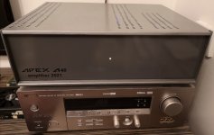
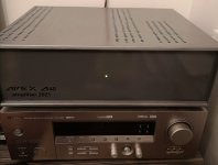
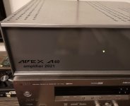
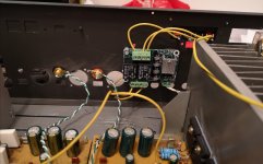
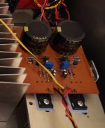
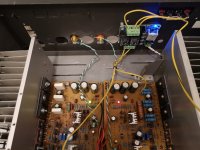
I'm listening Apex A40 for the better part of 2021, +/- 45V for now. Apex PS 15, speaker protection. I still have some work to do, but I just enjoy it for now. 🙂
Attachments
-
 IMG_20211224_204049.jpg241.5 KB · Views: 355
 -
 IMG_20211224_204117.jpg266 KB · Views: 325
 -
 IMG_20211224_204028.jpg291.2 KB · Views: 333
 -
 IMG_20211224_204000.jpg305.9 KB · Views: 346
 -
 IMG_20211224_204843.jpg246.4 KB · Views: 451
 -
 IMG_20211207_204735.jpg454.7 KB · Views: 467
 -
 IMG_20211207_204724.jpg395.5 KB · Views: 480
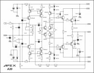
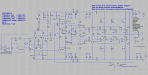
I modified AX20 for you. I did not make many changing as possible. For compensation, I use TMC. And output transistors I use 3 pair, so it can drive 2 ohm speaker and reduce distortion a bit at 8 ohm. D3 to make a clean clipping, I add resistor in series, because this diode reduce the slew rate. So the result, slew rate is relative high. I'm not a fan of super-pair Baxandall VAS in this topology, because using 2EF as VAS in this topology can reduce distortion in high frequency. But super-pair Baxandall VAS can add more H2 distortion.Bimo, Which model has low distortion at high frequencies? what scheme are you talking about?
You can improve this modification with cascode in the input, bootstrapping in pre-driver and driver transistors at output stage, etc. But of course it make complicated.
Attachments
Hi,,,TL for 8 inch driver.
Any recommendations for the drivers?
Bimo,
Here I see a more complex correction (c33, c34, r52, R51) - did it not work with the usual one, as in the original scheme? is this a two-pole correction?
C7 - is definitely needed for such a large nominal value? is a 1-4 uf film not suitable? C35, C36 - not too big?
Here I see a more complex correction (c33, c34, r52, R51) - did it not work with the usual one, as in the original scheme? is this a two-pole correction?
C7 - is definitely needed for such a large nominal value? is a 1-4 uf film not suitable? C35, C36 - not too big?
"modification with cascode in the input" -let's add this, too, how to calculate it - where can I read it?
It is TMC and I already implemented in another amplifier.Bimo,
Here I see a more complex correction (c33, c34, r52, R51) - did it not work with the usual one, as in the original scheme? is this a two-pole correction?
C7 - is definitely needed for such a large nominal value? is a 1-4 uf film not suitable? C35, C36 - not too big?
You need to read a book from Bob Cordell, Douglas Self, or Dr. Arto Kolinummi."modification with cascode in the input" -let's add this, too, how to calculate it - where can I read it?
It is TMC and I already implemented in another amplifier.
how does the abbreviation TMC stand for?
I didn't see the methodology there, although I may have looked at it inattentively...Douglas Self
TMC = Transitional Miller Compensation.how does the abbreviation TMC stand for?
You can ask Douglas Self and Bob Cordell here, because they are member of this forum. A thread in this forum talk about Bob Cordell book. If you do not believe me, please do not PM me and ask some help. I have design amplifiers with many topology with many compensations. Not all of them I build my self. Some built by local audio community here. Although, if the schematic is good it doesn't mean the result is always good. Because pcb layout, components choice, and the power supply have influence to the result.I didn't see the methodology there, although I may have looked at it inattentively...
- Home
- Amplifiers
- Solid State
- 100W Ultimate Fidelity Amplifier