OK so it is to include the LED?
LED is off if relay is on
Safe version
Does this work as a soft start? Or only on/off?
Does this work as a soft start? Or only on/off?
Only on/off function. You should add another relay and delay circuit for soft start. My 2 cents.
Please explain the purpose of this circuit and why a simple 12vdc transformer, relay and a switch wouldn't do the same thing.
This is to be used with a touch-on/touch-off button, like on a desktop PC. So, this circuit is in stand-by mode all the time. Sorry if I am preaching to the converted.
Last edited:
This is to be used with a touch on/touch off button, like on a desktop PC. So, this circuit is in stand-by mode all the time. Sorry if I am preaching to the converted.
Thanks, it is all clear now.
Another AX14...
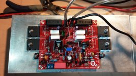
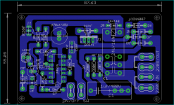
Completed assembly of a pair of AX14 boards. Prasi board design from post 11462. Thank you Apex for the amp design and prasi for creating the board layout and sharing at pcbway. The boards are very nicely made. All components fit well and the layout is very well done. The BOM was also helpful for finding a few specific components such as the 0.33 ohm 5 watt resistors and the heatsinks for Q8 & Q9. Thank you prasi for sharing the BOM also.
These are using original Toshiba driver (2SC4793 / 2SA1837) and output transistors (2SC5200 / 2SA1943), salvaged from a Realistic PA250 amp. The power supply is regulated (LM338) +- 35V, for initial test run. I also have 500VA linear CRC power supply with +-55V rails for future use.
Both boards started up as expected with no issues. Initial testing was using 10ohm, 1 watt resistors in place of fuses to check basic functions. After that, fuses were reinstalled. DC offset is stable at 5.3mV left channel and 7mV right. Dialed in about 125mA of bias current and played music for over an hour. Will try lower bias adjustments but the heatsink temps seem to be staying at about 116 deg F (47 C).
This first evaluation is very good. Near silence with music paused. I can hear the slightest hiss with ear almost touching the tweeter. Very acceptable considering that this amp is with no case and wires are a mess. The midrange and highs are exceptional, making vocals and stringed instruments sound very dynamic with excellent imaging. Bass is good, with nothing lacking. This amp is very clear and gets loud without realizing. So far I'm very satisfied with this build. A fairly easy to build amp that works very well.
Attachments
Safe version
Is this the circuit for this ? It will be more safe if the circuit always accompanies the PCB !
Attachments
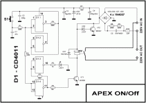

Is this the circuit for this ? It will be more safe if the circuit always accompanies the PCB !
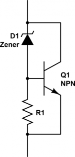
No need for a resistor to complete the power zener?
Attachments
Sir miles can i use this off/on to any kind of power amp sir? thanksSafe version
Safe version
Safe version pcb files.
Attachments
Completed assembly of a pair of AX14 boards. Prasi board design from post 11462. Thank you Apex for the amp design and prasi for creating the board layout and sharing at pcbway. The boards are very nicely made. All components fit well and the layout is very well done. The BOM was also helpful for finding a few specific components such as the 0.33 ohm 5 watt resistors and the heatsinks for Q8 & Q9. Thank you prasi for sharing the BOM also.
These are using original Toshiba driver (2SC4793 / 2SA1837) and output transistors (2SC5200 / 2SA1943), salvaged from a Realistic PA250 amp. The power supply is regulated (LM338) +- 35V, for initial test run. I also have 500VA linear CRC power supply with +-55V rails for future use.
Both boards started up as expected with no issues. Initial testing was using 10ohm, 1 watt resistors in place of fuses to check basic functions. After that, fuses were reinstalled. DC offset is stable at 5.3mV left channel and 7mV right. Dialed in about 125mA of bias current and played music for over an hour. Will try lower bias adjustments but the heatsink temps seem to be staying at about 116 deg F (47 C).
This first evaluation is very good. Near silence with music paused. I can hear the slightest hiss with ear almost touching the tweeter. Very acceptable considering that this amp is with no case and wires are a mess. The midrange and highs are exceptional, making vocals and stringed instruments sound very dynamic with excellent imaging. Bass is good, with nothing lacking. This amp is very clear and gets loud without realizing. So far I'm very satisfied with this build. A fairly easy to build amp that works very well.
Nice build there dirttracker...thanks for the kind words. happy that build is done without any issues.
Q10 BD139 needs to be mounted on one of the output devices using the same bolt via short wires .
You could play around with grounding scheme once you finalize the build (like connecting input ground directly to PSU ground after disconnecting it from amp PGND.. second is remove the 10R ground lift and connect directly via jumper to PGND, etc).
Happy listening.
le falto su red de zobel al a33
 English only please. Rules.
lacking its network of zobel at a33
Hi Prasi,
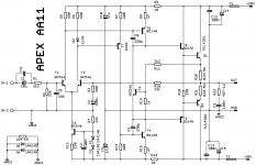
On the AX14 board, for R26 which is rated 10 R 2W as per the schematic. Can I use a metal oxide flameproof resistor? As I have them in stock and not any metal film ones.
Thanks
On the AX14 board, for R26 which is rated 10 R 2W as per the schematic. Can I use a metal oxide flameproof resistor? As I have them in stock and not any metal film ones.
Thanks
Hello Manniraj,
its zobel resistor , so not at very critical from tolerance and type.. You may use anything of highest wattage you may find in your parts bin that fits suitably.
regards
Prasi
its zobel resistor , so not at very critical from tolerance and type.. You may use anything of highest wattage you may find in your parts bin that fits suitably.
regards
Prasi
just try..LED is off if relay is on
Attachments
- Home
- Amplifiers
- Solid State
- 100W Ultimate Fidelity Amplifier