files??😕
U say u need the and PSU .So I uploaded file PDF.that files
just connect the meter across resistor (parallel ) to resistor.
For Bias reading
https://www.diyaudio.com/forums/sol...imate-fidelity-amplifier-893.html#post4870433
Greetings to all,
Apex DC555- Post #8925
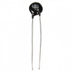
Is this the correct NTC for Apex DC555?
How to fix this on heatsink?
for zobel network, please let me know coil description.
Thank You
Greetings to all,
Apex DC555- Post #8925
Is this the correct NTC for Apex DC555?
How to fix this on heatsink?
for zobel network, please let me know coil description.
Thank You
Attachments
Here are the files for DIY for anyone, for the FX-8 mod by Bimo.
Here are the layout considerations,
1. 470u/220u caps have 13mm dia x 5mm pitch.
2. 1uF caps have 5mm or 7.5mm pitch.
3. On board inductor of ~13-14mm dia
4. holes for optional 10mm pitch silver mica caps
5. 3296W MT trimmer.
6. 0.5 w res have min pitch of 10mm, 1w has 15mm, 2w has 18mm
reg
Prasi
Can I use 2SK135/2SJ35 for the final?
hello
i need a tone control for class D amplifier with tda7498 ic
any suggestion ?
Use this circuit
Attachments
Use this circuit
hi mr Mile
thank you for your suggestion
can you suggestion an professional tone control for this class D amplifier?
i want use it in my car and my PSU is an boost topology
Hi, yes you can, 35-0-35 VAC it means 48-0-48 VDC
I have tested it at +/-53v and it works well. Look for FH9HV. Change dome components for higher voltage.
100W Ultimate Fidelity Amplifier
Hello Apexaudio,
I was try Apex FA9, the sound was amazing.
Now have a pairs of 2SK135/2SJ50 mosfet.
Any recommended layout?
Thanks you
I was try Apex FA9, the sound was amazing.
Now have a pairs of 2SK135/2SJ50 mosfet.
Any recommended layout?
Thanks you
Hello Apexaudio,
I was try Apex FA9, the sound was amazing.
Now have a pairs of 2SK135/2SJ50 mosfet.
Any recommended layout?
Thanks you
FX8
Ultimate Noob Questions
First some background: I'm a guy in his early sixties, over the last couple of years I've taken an interest in learning electronics, and more recently in diy audio. I started by building cheap kits from the internet, electronic dice, led kits, clock kits and a couple of radio radio kits (AM and FM). This taught me how to solder and I've also done a bit of smd soldering.
My first venture into diy audio was assembling chip amp kits, I then etched some pcbs, sourced some components and built some diy chip amps. My first venture into solid state was a pair of JLM MX50 amps, I stuck them in a case with a toroidal transformer and a diy rectifier filter PS. This has been my main amp for about a year now.
Which brings me to the point of my post (at last I hear you cry), I wanted to build a retro amp so I etched the boards for an AX6, the FH9 also looked interesting so I've etched those too (components are incoming). Now with the class D chip amps I built there's no need to worry about setting bias or offset, not so with the AX6 and FH9, for these are very different beasts.
I've read through all 61 pages of the AX6 thread and for the life of me I can't find any explanation of how to set the bias and offset. The same goes for the FH9, although I'm only at page 796 of 1109, there are so many different amps in this thread it's sometimes difficult to tell which amp a post refers to.
I understand I'm probably (definitely) over my head with these two builds, however I'd greatly appreciate any help in setting them up. For the moment I've set the pots to their mid point.
Many thanks,
Graham
I've read through all 61 pages of the AX6 thread and for the life of me I can't find any explanation of how to set the bias and offset.
Many thanks,
Graham
For the ax6 DC balance, I think some of the later layouts had a trimmer. Otherwise a 15k resistor in R5 worked for me to get equal 24v rails (using a 48v supply).
For the bias, measure the millivolts across the 0.47 ohm resistor R18(?) using Ohms law, I=V/R, 10mV will give you around 20mA. I think it was Thimios that had good results with around 14mA but the recommendation was in the region of 20-50mA.
Also make sure you don't have R8 and R8' populated at the same time (trimmer and fixed value resistor) - use the trimmer then determine the resistance and replace trimmer with that value (if you want to make the bias fixed).
I'm not familiar with the FH9 but the process tends to be similar.
And everyone is a noob at the beginning. Treat any failure as an opportunity to learn (even though it can be frustrating as hell) and enjoy!
Hello Graham,
Please refer following posts for adjustments of Bias and mid point voltage for the APEX AX 6.
Mid point voltage Retro Amp 50W Single Supply
Bias: please see upper left corner of silk screen of PCB (R8 and R8')
Retro Amp 50W Single Supply
As mentioned by avtech and somewhere in the thread also 14mA was plenty of Bias for member thimios for no crossover distortion. As mentioned by me in the thread, 20-50 mA is ok.
I also have some PCBs for that amp. If anyone is interested, willing to give away free of cost , just the shipping. I need to clear the clutter in my apartment to maintain WAF at acceptable levels😉.
With the New Tarkus speakers in the house, WAF is all time low🙁
Regards
Prasi
Last edited:
avtech23/Prasi,
Thanks for the replies, this is exactly the info I needed. I hope to complete both boards next week, it would have been this weekend but the components I ordered are being delivered today while I'm out.
Many thanks,
Graham
Thanks for the replies, this is exactly the info I needed. I hope to complete both boards next week, it would have been this weekend but the components I ordered are being delivered today while I'm out.
Many thanks,
Graham
Hi guys,
any of you have any ready-made AX14 PCB, and can you send them?
Thanks
you could order it from here
100W Ultimate Fidelity Amplifier
prasi


1st short input. 2nd disconnected speaker. 3rd set multimeter to millivolt. 4th check across emitter resistor. See mili volts.
- Home
- Amplifiers
- Solid State
- 100W Ultimate Fidelity Amplifier