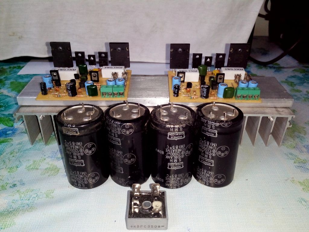
Hello I have a multiple side cap board if you want to try out here are the files
make no sense to have them collecting dust in a USB driver 😛
I already mark the drilling for those caps 🙂
Regards
Juan
make no sense to have them collecting dust in a USB driver 😛
I already mark the drilling for those caps 🙂
Regards
Juan
Attachments
Hi Juan
Thank you for this board layout
I have some of those TO-220 diode
That will surely fit for this layout🙂
Thank you for this board layout
I have some of those TO-220 diode
That will surely fit for this layout🙂
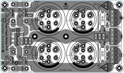
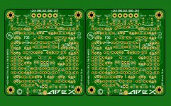
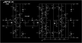
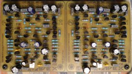
P30 line amplifier board
Time for new PCB ,not tested yet ,maybe some errors ......🙂
At usual a small contribution from me 😉
Regards,Alex
Time for new PCB ,not tested yet ,maybe some errors ......🙂
At usual a small contribution from me 😉
Regards,Alex
Attachments
Time for new PCB ,not tested yet ,maybe some errors ......🙂
At usual a small contribution from me 😉
Regards,Alex
Nice work as usual.
Regards

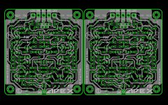
And for us, poor DIYers that etch our own boards at home, could you kindly place a B&W print of the PCB layout?
TYVM!!!
TYVM!!!
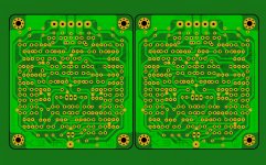
Thank all , and here are all files for toner transfer , for those who want to build this line amplifier ...🙂 PCB it's correct ,no mistakes bot not tested .
Regards ,Alex
Regards ,Alex
Attachments

Gee Terry, you have that process working well, cheers to you.
I'm getting better at it. I saw a little video on youtube where the guy used cheap shelving paper from the dollar store. I tried it and it is wonderful. I used to print onto paper and then iron it. Then I would have to scrub the paper off the boards, With the shelf paper the image releases from it completely so there is nothing left on the boards but toner. Very little touch up required. I also started using the 2/1 mixture of hydrogen peroxide and muriatic acid. Takes 5 or 6 minutes to do the job and it is dirt cheap.
Hi Alex,
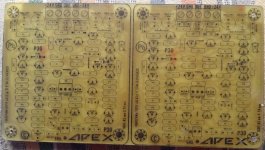
Thanks again for being so kind in sharing your hard work with us. I have a question if I may. After drilling the first board I turned it over to look for missed holes and noticed that your have 4 hole per resistor. May I ask what the two in the center are for? Are there some new resistors that have that footprint?
Thanks, Terry
thx terry, great info, i tried the iron on method, it did not work well. i do have a laser printer now samsung clp-510, so i might give your method a try, now you figured out the process
i assume the dual r footprint is for different physical sized r comps. i use old philips sfr16/25 series r's for very tight tht layouts, rn/mrs series r's are much bigger.
i assume the dual r footprint is for different physical sized r comps. i use old philips sfr16/25 series r's for very tight tht layouts, rn/mrs series r's are much bigger.
[QUOTE
Hi Alex,
Thanks again for being so kind in sharing your hard work with us. I have a question if I may. After drilling the first board I turned it over to look for missed holes and noticed that your have 4 hole per resistor. May I ask what the two in the center are for? Are there some new resistors that have that footprint?
Thanks, Terry[/QUOTE]
Hi Terry,
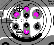
Those four pads for each resistors are for different mounting ,larger for horizontal resistors ,and the closer two pads for vertical one ...... 😉
Regards,Alex
Hi Alex,
Thanks again for being so kind in sharing your hard work with us. I have a question if I may. After drilling the first board I turned it over to look for missed holes and noticed that your have 4 hole per resistor. May I ask what the two in the center are for? Are there some new resistors that have that footprint?
Thanks, Terry[/QUOTE]
Hi Terry,
Those four pads for each resistors are for different mounting ,larger for horizontal resistors ,and the closer two pads for vertical one ...... 😉
Regards,Alex
Thanks Alex. I had thought that but I haven't seen vertical mounting except on small boards where there was not room to lay them down. I thought maybe there was an axial version I didn't know about.
I have them drilled but family calls so I will have to wait until tomorrow to populate them.
Blessings, Terry
I have them drilled but family calls so I will have to wait until tomorrow to populate them.
Blessings, Terry
Wow, this little board has a lot of parts. 😱
I have a couple questions.
Will +-25V rails work?
I don't have any 100K pots. Will 50K log pots work?
I have a couple questions.
Will +-25V rails work?
I don't have any 100K pots. Will 50K log pots work?
Attachments
Last edited:
- Home
- Amplifiers
- Solid State
- 100W Ultimate Fidelity Amplifier