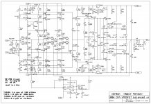
This amp is an evolution based on similar 100W CFA with unbalanced input only. It is possible to add an input balanced to unbalanced converter, but why not use the same electronic configuration to get it. CFA has very low impedance minus input not suitable to be used as balanced cold input. I used additional buffers to get high impedance cold input and in the same time to preserve CFA characteristic. I never saw something similar, but I could be wrong. By adding those buffers distortion did not increase.
To high CMRR, what is characteristic of balanced drive, it's very important to have very close hot and cold inputs impedances and there should be used 0.1% tolerance resistors.
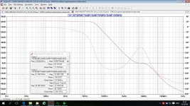
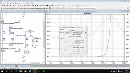
Here is the schematic, the Loop Gain and Close Loop Gain (balance drive) plots.
Damir
To high CMRR, what is characteristic of balanced drive, it's very important to have very close hot and cold inputs impedances and there should be used 0.1% tolerance resistors.
Here is the schematic, the Loop Gain and Close Loop Gain (balance drive) plots.
Damir
Attachments

Some more plots.
Attachments
-
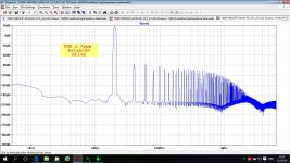
 100W CFA MOSFET -1-2-balancedin-FFT1k-1W-balanced-drive.jpg181.8 KB · Views: 652
 -
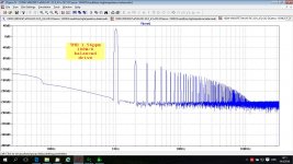
 100W CFA MOSFET -1-2-balancedin-FFT20k-1W-balanced-drive.jpg181 KB · Views: 631
 -
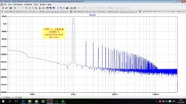
 100W CFA MOSFET -1-2-balancedin-FFT20k-100W-balanced-drive.jpg191.9 KB · Views: 231
 -
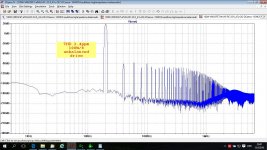
 100W CFA MOSFET -1-2-balancedin-FFT1k-100W-balanced-drive.jpg191.5 KB · Views: 235
It is quite easy to use this amp with unbalanced input, just connect cold input (or hot input for inverting work) to the ground.
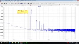
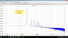
Here are FFT plots.
Here are FFT plots.
Attachments
well, if you do balanced inputs, you may as well do "balanced" outputs, too
🙂 🙂 🙂
thanks for sharing!
mlloyd1
🙂 🙂 🙂
thanks for sharing!
mlloyd1
well, if you do balanced inputs, you may as well do "balanced" outputs, too
🙂 🙂 🙂
thanks for sharing!
mlloyd1
Why I would do that?
By the way, with two of this amps it's easy to make it work in a bridge mode, just drive it unbalanced, one from the hot input(+ input) and other from the cold input (- input) and connect a loudspeaker between the outputs. No need for additional circuitry.
Last edited:
Not that I want to ruin your fun, but it's actually not current feedback, to become that you need to remove Q9, Q18, Q20 & Q22.
My experience is that the cascode of the input circuit current sources are not really needed with the low input voltage swing and heavy feedback.
See also the circuit of t.ex. the LT1364....
For lower noise you might also consider the BC327-40 / BC337-40 or the 2SA970 / 2SC2240 you're already using, in combination with lowering the feedback resistance....
Last edited:
Not that I want to ruin your fun, but it's actually not current feedback, to become that you need to remove Q9, Q18, Q20 & Q22.
My experience is that the cascode of the input circuit current sources are not really needed with the low input voltage swing and heavy feedback.
See also the circuit of t.ex. the LT1364....
For lower noise you might also consider the BC327-40 / BC337-40 or the 2SA970 / 2SC2240 you're already using, in combination with lowering the feedback resistance....
Don't worry, anyhow CFA and VFA are not the best way to describe amp topology, but I don't want to go into that discussion again.
I've have make similar configuration as in LT1364 or LT1363 op amp in my other design, look here http://www.diyaudio.com/forums/solid-state/253039-unique-cfa-120-230w-amp-16.html#post4428619 and I saw similar op amp (bastard CFA/VFA) later, just some idea came to me without knowing that everything was done before.
The cascode lower THD considerable and permit to use complementary transistors BC550/560 for the input super pairs. I don't see why BC327-40/337-40 would be better suited for that job with higher Cob and not low noise types.
I tried different feedback resistance, and chose this as a compromise. You can notice that lower resistor(R73) is not connected to the ground but to the buffer output, and output impedance influences the feedback ratio. With to low feedback resistors this influence is to high.
That cold input buffer is something I haven't seen to be used before.
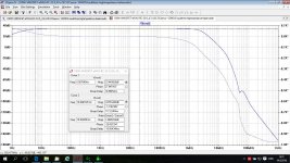
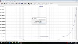
How's the PSRR?
PSRR!
Attachments

Erratum?
Please accept my compliments on yet another intriguing circuit and my thanks for publishing all your interesting and enjoyable designs.
In the schematic diagram of the first post, as drawn; is Q36 correct?
Please accept my compliments on yet another intriguing circuit and my thanks for publishing all your interesting and enjoyable designs.
In the schematic diagram of the first post, as drawn; is Q36 correct?
PSRR!
Was any output load connected for this plot? Also was there any signal present? I've found both make a difference to the result, though having an output load makes almost no difference at all with no signal present.
Please accept my compliments on yet another intriguing circuit and my thanks for publishing all your interesting and enjoyable designs.
In the schematic diagram of the first post, as drawn; is Q36 correct?
You have very sharp eye, of course it is up side down. In the simulation, schematic was correct, of course.
Here is corrected schematic.
Attachments
Last edited:
Was any output load connected for this plot? Also was there any signal present? I've found both make a difference to the result, though having an output load makes almost no difference at all with no signal present.
Output load was connected, 8 ohm, but the input signal level and the load do not influence LTspice PSRR simulation.
Don't worry, anyhow CFA and VFA are not the best way to describe amp topology, but I don't want to go into that discussion again.
I've have make similar configuration as in LT1364 or LT1363 op amp in my other design, look here http://www.diyaudio.com/forums/solid-state/253039-unique-cfa-120-230w-amp-16.html#post4428619 and I saw similar op amp (bastard CFA/VFA) later, just some idea came to me without knowing that everything was done before.
The cascode lower THD considerable and permit to use complementary transistors BC550/560 for the input super pairs. I don't see why BC327-40/337-40 would be better suited for that job with higher Cob and not low noise types.
I tried different feedback resistance, and chose this as a compromise. You can notice that lower resistor(R73) is not connected to the ground but to the buffer output, and output impedance influences the feedback ratio. With to low feedback resistors this influence is to high.
That cold input buffer is something I haven't seen to be used before.
I'm not talking about the cascade on the output of the input circuit, but the cascade on the current sources, Q17,Q24,Q30,Q19,Q25 & Q27, those are not really needed....
You might want to read the interesting thread here on low noise transistors, in transistors, noise is mostly related to Rbb, and the BC327/BC337 are driver transistors with low Rbb and therefore with significant lower noise than the BC550/BC560, although they're not specified as low noise.
Or get the 3rd edition of "The Art of Electronics", very interesting chapter on transistor noise....
A lot of designers ignore noise in power amplifier, I like sensitive speakers so noise matters to me.... With very few changes you could improve noise level significant, but hey, it's your design....
Could you support that claim with some data about noise superiority of the BC327/337 over BC550/560. For sure thy are inferior in Cob for about 5 times.
Regarding those, according to you redundant transistors, together with diodes are current mirror and improve temperature stability of the CCS.
Here is noise simulation of the amp.
Attachments
Just simulated SA2015. Noise is a little bit lower using BC3x7-40, but distortion increases. (BC3x7-40 have higher Cob, lower ft compared to BC5x0C)
And: the Onsemi BC550C parts do have lower rbb - unfortunately they are now unobtanium.
BR, Toni
And: the Onsemi BC550C parts do have lower rbb - unfortunately they are now unobtanium.
BR, Toni
Could you support that claim with some data about noise superiority of the BC327/337 over BC550/560. For sure thy are inferior in Cob for about 5 times.
"The Art of Electronics" have a page with actual measured noise data on a number of transistors, unfortunately not the BC327/BC337, but a number of similar parts. And the BC550/BC560, those are the most noisy.... In the used circuit, Cob of 5 pF or 1.5 pF doesn't matter much, especially as there is not much voltage swing on them....
I'm actually planning to measure the BC327/BC337 myself as I'm planning to use them (or more exact, their SMT equivalents....), seems like a pretty good part and they cost nothing....
Regarding those, according to you redundant transistors, together with diodes are current mirror and improve temperature stability of the CCS.
Here is noise simulation of the amp.
With 20 mW over them ? The current source transistors temperature coefficent is about the opposite of the LED reference anyway....
And btw, don't trust noise simulation, most models don't have correct Rbb so they model badly....
"The Art of Electronics" have a page with actual measured noise data on a number of transistors, unfortunately not the BC327/BC337, but a number of similar parts. And the BC550/BC560, those are the most noisy.... In the used circuit, Cob of 5 pF or 1.5 pF doesn't matter much, especially as there is not much voltage swing on them....
I'm actually planning to measure the BC327/BC337 myself as I'm planning to use them (or more exact, their SMT equivalents....), seems like a pretty good part and they cost nothing....
With 20 mW over them ? The current source transistors temperature coefficent is about the opposite of the LED reference anyway....
And btw, don't trust noise simulation, most models don't have correct Rbb so they model badly....
I plan to make SMT layout in near future, so if you have a list of recommended transistors, specially those for higher voltage and VAS I would appreciate it.
I used Cordells models for my simulation, but not sure how correct are rbb.
- Status
- Not open for further replies.
- Home
- Amplifiers
- Solid State
- 100W CFA mosfet with balanced input