Yes, since the bias voltage is higher (more negative), it requires a higher swing from the driver. The B+ is tube dependent as usual.
power torroids work fairly well as PP outputs, however the high frequency response rolls off at 15 to 30 khz depending on the brand and VA rating of the transformer. ( core materials )
if you get one of the 30khz capable ones, they can be excellent.
if you get one of the 30khz capable ones, they can be excellent.
811A, 811's, DA-42 are excellent as class B amplifiers the max voltage with the 811A is 600 volts at 70ma, the max for 811, DA-42, is 470-500volts as only 40 watts plate dissipation. for the 811A at 600 volts the P to plate load is 2K. has about 20 watts or more class A. These amps were used for record cutting. of course you need a cathode follower or mosfet driver for Grid current. You can use PL509 TV KT88 tubes and more driven on Grid 2 max voltage about 470 volts with 40 watts dissipation.
Hi Nigel. That's a cool amp. I like the way some in the community is exploring toroidals for output iron. Very inspirational. Good work my man!
It was to save on costs mainly.
I have used back to back power transformers for heaters and HVAC in the past and that worked great.
I came up with the idea of using a mains transformer backwards for the output transformer thinking it was great idea only to find many had got there before me !
I have used back to back power transformers for heaters and HVAC in the past and that worked great.
I came up with the idea of using a mains transformer backwards for the output transformer thinking it was great idea only to find many had got there before me !
It is push pull.
I used a power transformer as it is much cheaper and sounds ok.
hi
it is not classic push pull.How you Calculate 10 Watt?
hi
it is not classic push pull.How you Calculate 10 Watt?
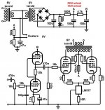
It is an LTP push pull. Listening to the amp I would guesstimate about 10 watts, it is loud for a living room. Secondary impedance is 8 ohms so that makes (from 240:12 transformer) 8*20*20 =3k2 primary impedance. And 226VDC B+.
So doing it simply 226*226/3200 =15 watts peak.
Last edited:
thanks ....but can you use lode and oscope to see ?output device should answer to signal .so it is better to see real power in secondary winding.
best impedance for el84 is 8k by data **** .some people use ac transformer for output !if we com back to tubes just for quilty .
if opt is expensive so we can winding .
best impedance for el84 is 8k by data **** .some people use ac transformer for output !if we com back to tubes just for quilty .
if opt is expensive so we can winding .
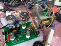
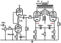
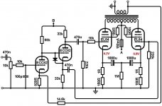
I recently acquired this amp kinda by accident, for spare parts. But after I received it I knew it looked familiar somehow and eventually traced it to this thread! So I thought it would be fun to run a few tests on it, and see what could be done with it. I had to reverse engineer the circuit, so Nigel can correct me if anything is wrong.
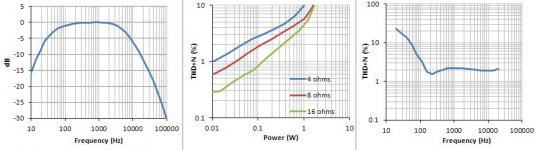
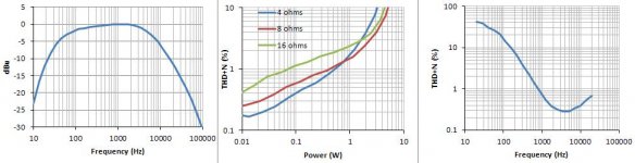
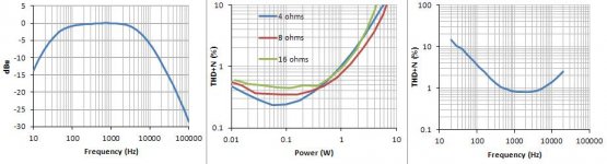
You can see from the results the -3dB bandwidth is about 40Hz to 6kHz (1Vrms into 8 ohms), which I guess isn't bad when you're using a power transformer as the output transformer.
Distortion is pretty dire, struggling to make even 1W if you don't mind listening to ~10% distortion!
In all the following tests, distortion v. frequency is also at 1Vrms into 8 ohms.
The main problem as I see it is that the HT is too low, only 141V! Let's bump it up a bit...
Attachments
Last edited:
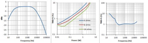
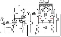
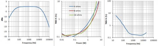
So I replaced the 9V backwards transformer with a 6V backwards transformer, giving me 220V HT. Now we're getting a more realiable 1W at close to 2% distortion @ 1kHz. At low frequencies it is actually worse, but it does looks better behaved -more like you expect for a transformer-coupled circuit.
I think the LM317 CCS is now the big handicap because it has barely any voltage headroom with only 6.5V across it. Also there is about 5mA mismatch between the EL84 cathode currents which could be affecting the output transformer, so let's do something about it...
I think the LM317 CCS is now the big handicap because it has barely any voltage headroom with only 6.5V across it. Also there is about 5mA mismatch between the EL84 cathode currents which could be affecting the output transformer, so let's do something about it...
Attachments
Last edited:
Yes, we know that a 230 V power transformer won't do too well as an OPT. I also think that this self-balancing PP design is sub-par as it strictly limits the power tubes' operation to class A.
Best regards!
Best regards!
Here I've replaced the CCS with individual bias resistors, but kept the cathodes coupled together with capacitors. Now there is only 1.3mA mismatch between cathode currents. Unfortunately this means we have sacrificed AC balance; without the CCS the master EL84 is passing much less signal to the slave EL84. Output power has suffered. So let's get rid of the trendy quasi-SRPP and restore AC balance with a proper phase inverter...
Attachments
Last edited:
OK this is now a big topological departure from the spirit of Nigel's orginal design, but a man's gotta do what a man's gotta do 😉
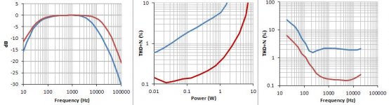
After converting the circuit to an old reliable DC-coupled cathodyne, we're really getting somewhere. Output power now comfortably manages 1W at <1% distortion, and distortion v. frequency is back to 'normal looking' again. If you don't mind listening to 10% distortion then we are getting 7W into 8 ohms, more than 4 times what we originally started with!
Finally let's do something about the frequency response. The limitation of the 'output transformer' could be improved either by driving it with a lower impedance, e.g. triodes, or by using negative feedback. Let's try the latter because it's quick and easy. From the previous frequency response graph it looks like about 8dB would be enough to bring the closed-loop response down to where it will manage 20kHz @ -3dB.
Attachments
Last edited:
So after adding 8dB feedback the response is now 35Hz to 15.8kHz, a bit less than attempted but hey, I didn't want to spend long on this or court instability. Remember, this is just for fun! Distortion has likewise fallen by 8dB, being less than 0.4% at 1W. You could now reasonably call this a 2W amplifier (~1% THD), at least at 1kHz! 😛
Hope you enjoyed the thread!
Hope you enjoyed the thread!
Attachments
Last edited:
We yet had to observe some FR improvement in the LF range after swapping that high impedance CCS for a serious PI 🙂.
Best regards!
Best regards!
With the transformer chosen, EL86 may be a better choice of output tube to match the lower reflected impedance.
Member
Joined 2009
Paid Member
So after adding 8dB feedback the response is now 35Hz to 15.8kHz, a bit less than attempted but hey, I didn't want to spend long on this or court instability. Remember, this is just for fun! Distortion has likewise fallen by 8dB, being less than 0.4% at 1W. You could now reasonably call this a 2W amplifier (~1% THD), at least at 1kHz! 😛
Hope you enjoyed the thread!
Nice work, some good learning here for us folks
- Home
- Amplifiers
- Tubes / Valves
- 10 watt valve amp project