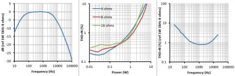
After the subject came up again in this thread, I thought I would go back to this circuit and show what happens when the output valves run in triode mode (gNFB removed). Here are the results. Compared with pentode mode in post 35, there is disappointingly little difference.
Attachments
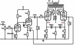
The toroid suspiciously performs like it was made with bifilar wound primaries, an unsafe and very bad cost reduction choice. Such design tend to have lower noise compared to regular winding practice when used as power transformer.
40+mA with 6V bias per tube? Looks like low plate voltage into 11-12K. In such case not good for EL84's in my experience.
Those results are not surprising and not the best one can get.
Because the EL84 in triode mode is not a 45 the practical trick is to find the sweet spot where the composite tube turns out to be linear in a wider area. IME, this is never happening with lowish plate voltage and high anode current. The suggested operative points in datasheets are a good starting point (i.e. 300V anode voltage with 20-30 mA max, to be found in practice). This is best done in practice with the actual tubes at hand as there might be significant variance with high sensitivity tubes like this.
That operative condition for the EL84 also makes life hard for the concertina as well and limits a lot the useful output power one can get with low distortion (less than 1%).
If the transformer can get some DC unbalance, the dynamic balance to minimize distortion even further can be done easily using low frequency (40-50Hz) square waves. But I can't see much room for this in that simplified amp.
The toroid suspiciously performs like it was made with bifilar wound primaries, an unsafe and very bad cost reduction choice. Such design tend to have lower noise compared to regular winding practice when used as power transformer.
All 120/240V primary power toroids are bifilar wound. And they are perfectly safe in general use all over Europe with the coils wired in series. Using two and interleaving the primaries I guess you could question and I still do to some degree - I’d like to see what the MTTF of that arrangement really is before I do it with say a 300 watt amp that costs real money. They were not intended to be used that way, but apparently Kodabmx and others have done it, but they won’t be beating on (and therefore heating) their amps like I will. OTOH, the normal voltage between turns on the HV secondaries of the cheap $57 Antek 400-500 volt power toroids is already that high and they don’t fail in normal use as power transformers. I’ve used them, and beat on them, so things are looking pretty good.
Because the EL84 in triode mode is not a 45 the practical trick is to find the sweet spot where the composite tube turns out to be linear in a wider area. IME, this is never happening with lowish plate voltage and high anode current. The suggested operative points in datasheets are a good starting point (i.e. 300V anode voltage with 20-30 mA max, to be found in practice). This is best done in practice with the actual tubes at hand as there might be significant variance with high sensitivity tubes like this.
He’s just up against the limitation of the primary winding voltage. 300V B+ is a little steep for a single 240VCT winding. True, toroids have puh-lenty of primary inductance - single digit Hz small signal response is no big deal. But you can’t apply the equivalent of more than 140 V RMS (200 peak) at 50 Hz across half the winding before saturation becomes an issue. That’s about where the primary current in normal use as a power transformer starts to skyrocket. If you want low distortion you need to back off more. for 300 volt or more B+ you really need two trafos interleaved to get the necessary magnetic headroom. They are only $17.50 each for Anteks, so springing for a second one would not he a deal breaker. And if it DID fail you’re only out $35 plus shipping.
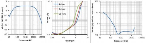
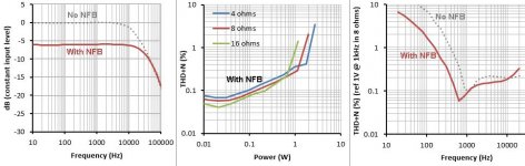
Well, I'm an idiot. I had desoldered the screen resistors and then put them back in exactly the same place -pentode mode! Ahem. Here are the corrected triode-mode results.Compared with pentode mode in post 35, there is disappointingly little difference.
Overall gain dropped by 9.5dB but bandwidth and THD have improved by not quite so much, which is what we expect for local rather than global feedback. This is something peculiar going on with THD v. frequency, which now shows a couple of cancellation nulls.
Attachments
Last edited:
Kodabmx and others have done it, but they won’t be beating on (and therefore heating) their amps like I will.
Don't be so sure. I run my stuff hot, and I like my music loud... 75°C is a normal chassis temperature on some of my amps - I even have a MOSFET SE amp that sits around 95°C.
Well, I'm an idiot. I had desoldered the screen resistors and then put them back in exactly the same place -pentode mode! Ahem. Here are the corrected triode-mode results.
Overall gain dropped by 9.5dB but bandwidth and THD have improved by not quite so much, which is what we expect for local rather than global feedback. This is something peculiar going on with THD v. frequency, which now shows a couple of cancellation nulls.
Any chance you tried (or can try) it with global feedback?
Not with ECC82, but any gNFB would be better than none. Maybe Merlin can change the first ECC82 to an EF86.
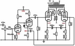
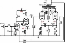
OK this is now a big topological departure from the spirit of Nigel's orginal design, but a man's gotta do what a man's gotta do 😉
.
why you put volume control on high impedance side of gain stage ? ,,,, and no emergency bias when that dial control fails ? ?? ?
Sure thing, but it's more of the same really. I removed the input cap because it was restricting the low frequency BW limit. Here are the results with about 6dB NFB added. I'm puzzled about what's happening on the THD v. frequency graph; I don't see any obvious signs of instability in the circuit but?Any chance you tried (or can try) it with global feedback?
Attachments
Interesting. I wonder how much of that is the transformer and how much is the ECC82. I'd be interested to see how it looks with a 6n1p, 6SN7, or ECC81.
Maybe I'll throw something together after the prep PCBs are populated.
Maybe I'll throw something together after the prep PCBs are populated.
Last edited:
- Home
- Amplifiers
- Tubes / Valves
- 10 watt valve amp project