Front Baffles
Hi Guys,
Sorry for the long pause since my last post. I'm into the construction phase of the project, which means things are going to slow down quite a bit.
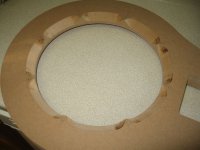
I just got my two front panels hot off the CNC machine. I can't stress enough how pleased I am with the quality and accuracy of the finished panels.
I took a chance and only left a few thou clearance between the outside edge of the drivers and the cutout specified in the drawing for the CNC, but the finished product is such a perfect fit that it makes me happy every time I place the tweeter in the baffle.
The work was done by a fellow who runs a local sign-making shop, and he only charged $70 for both baffles, which I thought was pretty fair.
If anyone else out there has drivers with odd-shaped baskets, I strongly suggest you take a look through your yellow pages for someone with a CNC router!
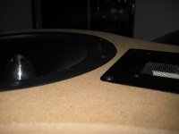
I have attached a few pictures of the finished front baffle with the drivers mounted.
The next step involves cutting out 32 additional shapes a little larger than the front baffles, then gluing them two at a time, and flush trimming to the original front baffle. As you can imagine, this is going to take quite a while, but the finished product should look excellent.
From what I've read on the other threads about the lamination process, I have to take great care to sand well between each flush trim, and make sure that the subsequent layers don't vary much from the original baffle. I'll be buying a really good Freud spiral up-cut flush trimming bit, and that should allow me to finish this whole project without the bit going dull.
I'll keep the pictures and updates coming as I progress with the work.
Cheers,
Owen
Hi Guys,
Sorry for the long pause since my last post. I'm into the construction phase of the project, which means things are going to slow down quite a bit.
I just got my two front panels hot off the CNC machine. I can't stress enough how pleased I am with the quality and accuracy of the finished panels.
I took a chance and only left a few thou clearance between the outside edge of the drivers and the cutout specified in the drawing for the CNC, but the finished product is such a perfect fit that it makes me happy every time I place the tweeter in the baffle.
The work was done by a fellow who runs a local sign-making shop, and he only charged $70 for both baffles, which I thought was pretty fair.
If anyone else out there has drivers with odd-shaped baskets, I strongly suggest you take a look through your yellow pages for someone with a CNC router!
I have attached a few pictures of the finished front baffle with the drivers mounted.
The next step involves cutting out 32 additional shapes a little larger than the front baffles, then gluing them two at a time, and flush trimming to the original front baffle. As you can imagine, this is going to take quite a while, but the finished product should look excellent.
From what I've read on the other threads about the lamination process, I have to take great care to sand well between each flush trim, and make sure that the subsequent layers don't vary much from the original baffle. I'll be buying a really good Freud spiral up-cut flush trimming bit, and that should allow me to finish this whole project without the bit going dull.
I'll keep the pictures and updates coming as I progress with the work.
Cheers,
Owen
Attachments

Hi Owen, looking good. On your lamination we often use 4-8 alignment holes where we can run a 1/4" dowel through all the pieces to help align them. You'll probably actually want to make all of your subsequent pieces first using just that front baffle as the template for all of them. Cut them all out, then start stacking them instead of gluing one up and then using the one you just glued as the template for each subsequent piece.
The more variation you put on the inside of each piece the better also. You can take a 45 degree miter bit and cut random notches on the inside edge of each piece you cutout. When it's all done you'll have lots of spikes all over inside to act like a diffuser.
John
The more variation you put on the inside of each piece the better also. You can take a 45 degree miter bit and cut random notches on the inside edge of each piece you cutout. When it's all done you'll have lots of spikes all over inside to act like a diffuser.
John
Maybe a dumb suggestion...
Why wouldn't you use a vibration absorbing glue between layers? Instead of the wooden dowels use metal studs so the assembly can be torqued by the nut on the end. If each layer is allowed to "float", albeit allowing only microscopic movements, then this would absorb energy within the system, reducing resonance and backwaves?
Why wouldn't you use a vibration absorbing glue between layers? Instead of the wooden dowels use metal studs so the assembly can be torqued by the nut on the end. If each layer is allowed to "float", albeit allowing only microscopic movements, then this would absorb energy within the system, reducing resonance and backwaves?
dpaws said:Maybe a dumb suggestion...
Why wouldn't you use a vibration absorbing glue between layers? Instead of the wooden dowels use metal studs so the assembly can be torqued by the nut on the end. If each layer is allowed to "float", albeit allowing only microscopic movements, then this would absorb energy within the system, reducing resonance and backwaves?
This could work in terms of helping absorb any cabinet resonance. The difficulty is then in finishing the cabinet. If you want to paint the cabinet, the seams between need to be sealed and rigid so they can't move and crack.
John
Mmm I suppose you'd have to coat the complete outer in the same goo and then build an external shell... gonna get heavy 🙁 Damn aesthetics!
If the "glue" was replaced by a soft sticky rubber gasket (laser cut) it could be trimmed to look good against the translam. The air tight seal would come from the torque ala engine head gasket... I'm feeling tangental!!!
If the "glue" was replaced by a soft sticky rubber gasket (laser cut) it could be trimmed to look good against the translam. The air tight seal would come from the torque ala engine head gasket... I'm feeling tangental!!!
Sealed boxes
Hi Guys,
I'm just drawing up the remaining sheets to be cutout, and I've got a few quick questions for either Linesource or anyone else who has experience with 0.7 sealed enclosures.
I worked out the volume I need for each TD10M, and it's a rather small 0.3 cubic feet to get a Qtc of 0.707.
The specs for my TD10M's seem to be:
Fs: 32 Hz
Vas: 2.08 cubic feet
Qts: 0.25
Does this seem correct? I'm also getting a system F3 of about 90Hz, which lets me either EQ the TD10M's, or simply add a subwoofer which is the more likely option.
I have an pretty accurate CAD model of the TD10M so I can easily get a very good number for the volume the driver occupies, which should let me get pretty close to my target.
My last question is about enclosure shape. John, you mentioned scalloping each layer randomly to get an uneven surface, but is there anything else I should be doing? I have a lot of control over the shape since it's made of laminated sheets, and I'd like to take advantage of that. Should I aim for a sphere shape behind the woofer, a tapered cylinder, a flare possibly? It's a rather small sealed box, so I'm not sure how much it matters, but I might as well do my best.
I'm getting the various layers cut this week, and I'll be doing some assembly work this coming weekend since I'll have access to a shop and a good router.
dpaws:
I like your suggestions with the boundary layer type assembly, but as john mentioned, finishing would be a problem. If you used baltic birch and the layers, it might look pretty cool on its own. I'm not sure what you could use between layers either. It would have to be compliant enough to seal, but hard enough not to deform much.
Cheers,
Owen
Not going to be a great help, but I have TD12M's and when I model for sealed box between .56-.7 I get a damn small box too. In fact, I asked about this on the AES forum and JohnJ said basically to not worry too much about it.
Off to a good start
Hi Guys,
I spent all last weekend working on these, and things are progressing slowly but well.
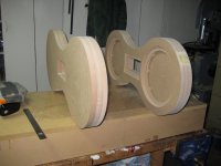
I've attached a few pictures of the building process, which show the first three layers that I managed to finish.
It's a painfully slow process, but there's something strangely rewarding about it. I'm only about 1/6th of the way done, and I could have easily built two normal boxes in the time it took me to get this far. Still, the end should hopefully justify the means.
Here's the process I've been using:
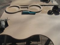
1. I had the front panel of each speaker cut out on a CNC router table from a Solidworks drawing.
2. I traced that shape, using the existing front panel, onto a sheet of MDF and then cut the traced shapes out with a jig saw, leaving about 1/8" of wood outside the trace lines.
3. I glued the jig saw cut out sheet to the back of the original, using two flat surfaces and a lot of weight. I decided using clamps was a bad idea given the large surface area, and the tendency that MDF has to crush/warp under clamping pressure. There's about 250 lbs of weight spread evenly over the surface, and that's just enough to cause a little bit of squeeze out from the joint. I used two small brad nails to hold the sheets in place so they wouldn't slide around with the weight on top.
4. Once the glue was set up, I took the part (now two layers thick) and flush trimmed all surfaces using the front panel as a guide.
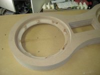
5. After flush trimming, I scalloped the rear of the second panel to increase the amount of space for air flow behind the TD10M's. To do the scalloping, I placed the driver in the hole, marked the bolt holes, drew a line from each marked hole to the inside of the cutout, then used a 45 degree chamfer bit to scallop starting on the line made from one bolt, and ending on the next. This method makes for nice even cuts.
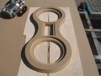
6. I then glued on a third layer, but this time, I didn't cut out the holes for the woofers. This third layer would be the layer which defined the inner diameter for each woofer chamber for the rest of the cabinet, so I couldn't just flush trim to the inside diameter anymore. Instead, after the glue dried, I flush trimmed the outer shape, found the centre of each circle, then used a Jasper Jig to cut two new holes in the back which would define the size of the enclosure for each woofer. Each subsequent layer can now just be flush trimmed to this size, until the cabinet is deep enough. The pictures probably explain it better than I just did.
7. The next step is to trace the new shape several more times, cut each out with a jig saw, then glue and flush trim each panel, one at a time.
I'll attached the pictures now, and I'll talk about the TD10M chamber after that.
Cheers,
Owen
Hi Guys,
I spent all last weekend working on these, and things are progressing slowly but well.
I've attached a few pictures of the building process, which show the first three layers that I managed to finish.
It's a painfully slow process, but there's something strangely rewarding about it. I'm only about 1/6th of the way done, and I could have easily built two normal boxes in the time it took me to get this far. Still, the end should hopefully justify the means.
Here's the process I've been using:
1. I had the front panel of each speaker cut out on a CNC router table from a Solidworks drawing.
2. I traced that shape, using the existing front panel, onto a sheet of MDF and then cut the traced shapes out with a jig saw, leaving about 1/8" of wood outside the trace lines.
3. I glued the jig saw cut out sheet to the back of the original, using two flat surfaces and a lot of weight. I decided using clamps was a bad idea given the large surface area, and the tendency that MDF has to crush/warp under clamping pressure. There's about 250 lbs of weight spread evenly over the surface, and that's just enough to cause a little bit of squeeze out from the joint. I used two small brad nails to hold the sheets in place so they wouldn't slide around with the weight on top.
4. Once the glue was set up, I took the part (now two layers thick) and flush trimmed all surfaces using the front panel as a guide.
5. After flush trimming, I scalloped the rear of the second panel to increase the amount of space for air flow behind the TD10M's. To do the scalloping, I placed the driver in the hole, marked the bolt holes, drew a line from each marked hole to the inside of the cutout, then used a 45 degree chamfer bit to scallop starting on the line made from one bolt, and ending on the next. This method makes for nice even cuts.
6. I then glued on a third layer, but this time, I didn't cut out the holes for the woofers. This third layer would be the layer which defined the inner diameter for each woofer chamber for the rest of the cabinet, so I couldn't just flush trim to the inside diameter anymore. Instead, after the glue dried, I flush trimmed the outer shape, found the centre of each circle, then used a Jasper Jig to cut two new holes in the back which would define the size of the enclosure for each woofer. Each subsequent layer can now just be flush trimmed to this size, until the cabinet is deep enough. The pictures probably explain it better than I just did.
7. The next step is to trace the new shape several more times, cut each out with a jig saw, then glue and flush trim each panel, one at a time.
I'll attached the pictures now, and I'll talk about the TD10M chamber after that.
Cheers,
Owen
Attachments
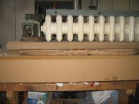
The "Clamp" in action.
The clamping setup used a nice flat base (and old, unfinished speaker cabinet), then the piece to be clamped, then two layers of 3/4" MDF to spread the weight, then about 250-300 lbs of random iron, like the cast iron radiator, an old vise, the table top from a table saw, and some other junk.
The clamping setup used a nice flat base (and old, unfinished speaker cabinet), then the piece to be clamped, then two layers of 3/4" MDF to spread the weight, then about 250-300 lbs of random iron, like the cast iron radiator, an old vise, the table top from a table saw, and some other junk.
Attachments


Well, that's about it for the picture update. I'd like to extend a big thanks to my dad, who was kind enough to let me use his tools, his workshop, and who helped to lift all that iron every time a layer had to be clamped. Without his help, all I would have is a pair of front panels taking up space in my office.
As for the main chamber, I'm still working through the ideal internal volume, so I'm not going to put too many more layers on before I decide on a shape and volume. My plan right now is to continue with the cylindrical shape for a few more layers, then gradually taper the shape back with smaller and smaller circles until it's a small point, kinda like the B&W enclosures. This will give me a small region where I can apply damping material on the flat cylindrical section, then I'll stuff the rest with long fiber wool.
Any advantage to supporting the rear of the driver? That' might be another option, but it's a huge hassle, and I don't want to do it unless I really have to.
Now for the subwoofer question. I've been mulling over the box tuning, and it looks like I'm most definitely going to need a pair of subwoofers to play along with these. The F3 on a 0.707 sealed box with the TD10M's is about 90Hz, so I'll have to integrate my subs with that.
Right now I'm thinking of an ELF style system with 18" drivers (Ciare NDC 18-4 S or 18 sound or B&C or FaitalPRO) and some 3kW subwoofer amplifiers. The amps have built in DSP modules, so I can easily make these flat to whatever the drivers and amplifiers can handle. I've been reading up on this style tuning, but I have a lot left to cover. Anyone with any experience can feel free to chime in!
Driver suggestions would also be very much appreciated. I'm focusing on PA drivers intended for subwoofer applications with decent Xmax, good power handling, and reasonably high efficiency.
Cheers,
Owen
opc said:As for the main chamber, I'm still working through the ideal internal volume, so I'm not going to put too many more layers on before I decide on a shape and volume. My plan right now is to continue with the cylindrical shape for a few more layers, then gradually taper the shape back with smaller and smaller circles until it's a small point, kinda like the B&W enclosures. This will give me a small region where I can apply damping material on the flat cylindrical section, then I'll stuff the rest with long fiber wool.
This is a fairly good option for helping in the midrange chamber. Either going to a point or to an axe head at the back of a rectangular enclosure. In terms of cleaning up the midrange reflections the best option is probably going to be packing the back tight with fiberglass insulation or rockwool.
Any advantage to supporting the rear of the driver? That' might be another option, but it's a huge hassle, and I don't want to do it unless I really have to.
I don't see a real need for this. If you wanted to, you could drill farther into the small center drill point in the back plate. Then tap it and screw in a 1/4-20 or even 3/8" set screw so you could bolt something to it. I don't see a need though.
Now for the subwoofer question. I've been mulling over the box tuning, and it looks like I'm most definitely going to need a pair of subwoofers to play along with these. The F3 on a 0.707 sealed box with the TD10M's is about 90Hz, so I'll have to integrate my subs with that.
If you stay sealed, you will want to work with a subwoofer. with DSP you can apply an easy filter and go a little lower, maybe 60-70hz if you wish.
Right now I'm thinking of an ELF style system with 18" drivers (Ciare NDC 18-4 S or 18 sound or B&C or FaitalPRO) and some 3kW subwoofer amplifiers. The amps have built in DSP modules, so I can easily make these flat to whatever the drivers and amplifiers can handle. I've been reading up on this style tuning, but I have a lot left to cover. Anyone with any experience can feel free to chime in!
I'm not a huge fan of the ELF type system as you lose a lot of the benefit to the efficiency you had. You also need massive amounts of power and power compression then becomes an issue. Larger enclosures are always going to give you more, lower distortion bass. Vented/PR enclosures typically even more. Again you need to determine your low end goals. If it is 30hz to cover the Low B on a bass guitar it is a lot different than if you want to play 16hz pipe organ notes.
If you want an 18" Prosound driver, Elite Audio has a bunch of B&C 18TBX100's they are selling cheap. They just upgraded them to 14 of our new TD18H+ drivers. Our new 18 has a full 14mm Xmax, full copper sleeve on the pole for low distortion and low power compression. Elite noted that they have about 3dB more output at high volume levels than they did with the B&C 18's. This is a combination of lower power compression and more linear Bl at high excursion. Pics are on these two links but haven't been resized yet.
http://www.aespeakers.com/pics/temp/PICT2823.JPG
http://www.aespeakers.com/pics/temp/PICT2825.JPG
Another option is a PR sub using an AV15 and dual 18" PR's such as this one I brought to the AVS get together back a month or so ago. You can read about the impressions beginning here.
http://www.avsforum.com/avs-vb/showthread.php?p=15938933#post15938933

Driver suggestions would also be very much appreciated. I'm focusing on PA drivers intended for subwoofer applications with decent Xmax, good power handling, and reasonably high efficiency.
I'd put the TD18H+ against any 18" driver with coils up to 4" diameter in terms of power handling and low power compression any day. The also have a large 2.5" x 5" long phase plug that would match the TD10M's. If you're looking at the ELF type system(which I wouldn't personally go that way as I said) you really want low efficiency though or you're needing to cut more down. If you had a 98dB prosound 18" driver, by the time you flattening the system to 20hz you may end up with 82-85dB.
John
I would suggest having
2 x http://www.madisound.com/catalog/product_info.php?manufacturers_id=150&products_id=843
in a WMTMW LR4 midrange range crossover at 200Hz and 3.2khz the result will be very clean and articulate critical midrange and clearing out the bass cone break up of the bass
2 x http://www.madisound.com/catalog/product_info.php?manufacturers_id=150&products_id=843
in a WMTMW LR4 midrange range crossover at 200Hz and 3.2khz the result will be very clean and articulate critical midrange and clearing out the bass cone break up of the bass
opc said:Any advantage to supporting the rear of the driver? That' might be another option, but it's a huge hassle, and I don't want to do it unless I really have to.
You mean bracing the magnet against the rear wall of the cabinet? It is sometimes done (notoriously by Camber) but the purpose was to minimize the transfer of vibrations from a driver with a stamped metal basket to a particleboard cabinet, all the while reinforcing said cabinet. The purpose was to achieve better rigidity using low-cost components, and it worked well.
But with a cast basket and braced MDF cabinet like yours it would probably be overkill.
- Status
- Not open for further replies.
- Home
- Loudspeakers
- Multi-Way
- 10" MTM with NeoPro5i Ribbon - Build Thread