No offense taken, rather its information everyone should have but few do unless they have done a lot of testing. I know it has frustrated me to no end to even get the same driver to test the same on different days. Now its all about environmental control and having a serious clamp and holding system for the driver to even get close to repeatability.
Try sweeping the B&C in a sealed box as the rising Fs of the driver in the box will probably meet that air flow problem and hide it.
Try sweeping the B&C in a sealed box as the rising Fs of the driver in the box will probably meet that air flow problem and hide it.
That is pretty strange behaviour on the B&C. I've measured the 8NDL51 which shares the same cooling vents and it doesn't show anything like that, in fact it matches the manufacturers specs very well. I do have a pair of 15NW76's that have not measured yet. I'll try to do that soon.
owen
i believe i have had the chance, about seven years ago, to listen to music on Altec "Voice of the Theater" speakers. i must say i have never heard or felt music so profoundly before or since. i love the idea of creating speakers that allow for that effect without the space consumption.
as well, the casing you've devised is extremely attractive. you're obviously as gifted an industrial designer as you are an engineer.
and the brazillian rosewood looks lovely, if politically incorrect..
jane
opc said:Here's the B&C 10NW64 impedance plot for two samples. Looks like Fs is right around 50Hz, and I think that bump at 200Hz has to do with the aforementioned voice coil cooling setup.
One of two things is going on there. My first guess if I saw that in most any driver is that it is a spider resonance. That is in the range that MANY drivers have these issues. It is something I dealt with in the first sample 6.5" spiders. If you want to spend a little money you can get a strobe like this and determine what is going on:
http://www.linearx.com/products/accessories/LS310/LS310_01.htm
It could very well have something to do with the venting as well though.
opc said:I've never really agreed with the whole "Ceramic has more thermal mass and therefor less power compression" train of thought. I would think that better air cooling around the coil would be a greater advantage. Both motors under heavy use in the same cabinet would eventually reach a thermal equilibrium, at which point I think the better air cooling would have an inherent advantage.
If you can suggest a way to thermally stress these without making to much noise I'll certainly give it a try.
There are quite a few things to look at besides just the mass of the magnet itself. The first thing you need to do is get the heat from the coil. Air is very poor at transferring heat. Airflow above the gap is a good thing, but it can only cool the part of the coil that is above the top plate. You can't force air up and down through the gap, which is where you need the cooling. Therefore you have to rely on heat transferring to the pole and top plate. The more surface area of the coil you have next to the surface area of the pole and top plate, the more efficient the transfer. The B&C has a 16mm long coil in an 8mm tall gap. Therefore 50% of the coil is adjacent to the top plate, and approximately 16sqcm total is adjacent to the steel on the OD. On the TD10M you have a 25mm long coil and 19mm tall gap. You have 75% of the coil in the gap and a total of over 32sqcm adjacent to the top plate. This gives much better heat sinking ability. This is the reason or 2" coil drivers are used on front of house systems getting as much as 1200W per driver on a continuous basis without failure.
That is the issue on the OD of the coil. On the ID of the coil it is totally different. The B&C uses a glass fiber form which is an insulator. It prevents heat from effectively traveling from the coil to the pole piece. The TD10M uses a black anodized aluminum former. This is thermally conductive and pulls heat from the windings right away. Again the amount of surface area we have here is very high. As we all know, black absorbs light, and while there is no visible light there is UV light created by heat that is absorbed. Then here is the biggest key. The entire pole is sleeved with copper. This copper is highly thermally conductive to quickly pull heat from the form and sink it into the large pole. This is the same concept as a frying pan with copper on the bottom. It more quickly absorbs heat and then directly transfers it to the pan.
Once the heat is away from the coil it has to have somewhere to go. As long as the pole and top plate are cooler than the coil, heat will continue to transfer. This is where the long term thermal constant would be significantly better in the TD10M. The motor has something like 5x the mass of steel that a driver like the B&C would have. This means that with the same amount of heat transferred from the coil to the motor the temperature of the motor will be magnitudes cooler in the TD10M. The larger motor then also means that there is significantly more surface area for the motor to radiate heat away to the surrounding air than with the B&C.
So to recap, much more area to pull heat from the coil. Then much greater conductivity to pull that heat to the motor. The motor has much more mass to distribute the heat. The surface area is much larger to radiate heat away to the surrounding air. Oh, and that doesn't even take into account the mass of the phase plug to pull heat from the pole quickly and it's ability to radiate it away to the moving air in front of the driver.
John
nickmckinney said:Something weird is going on with that B&C driver, I wonder if you removed the dustcap if that 200Hz problem would go away. You would lose the forced cooling I imagine though.
opc said:
The cooling system is indeed responsible for the strange behavior seen at 200Hz, and to be honest, it's pretty disappointing. With the vents sealed, the Fs obviously goes up, but the resonance at 200Hz is gone. The effect on the FR graph is even more pronounced. The driver now looks well behaved with a normal roll-off.
Regarding both of these comments, it is very possible that the cooling system is a problem, but it may very well be another issue as well. This looks like other drivers i've played with that have the spider issues. My actual guess is that it is both, some kind of spider resonance induced by the air flowing through that cooling system. Have someone hold their fingers and push down on the spider and take another impedance curve. If it changes, it's a spider issue you may be able to help out. If it stays the same then it isn't.
John
Hi Guys,
I've been running a little slow on these the last few days, as my test baffle really isn't big enough to measure the 10" drivers accurately. I have a pretty good idea of the response of the TD10M drivers by piecing together several response graphs, but I won't be publishing anything until I can measure under better circumstances. I'm definitely seeing the effects of baffle step in the lower midband.
If all goes well I should be making a trip to Toronto in the next week, where I'll get the chance to measure both the woofer and tweeter in one of the best anechoic chambers in North America. I should have very good graphs to publish then... one of the many benefits of having a job that's also your hobby.
Jane:
You're far too kind, and much more confident of my industrial design abilities than I am. I'm glad you agree with me on the Voice of the Theater sound, it really changed the way I felt about sound reproduction in general.
You're welcome to swing by for a listen when I get everything done, and you can let me know if I hit my mark or not.
John:
I know how important the thermal handling of the drivers is in PA applications, but luckily for me it will probably never be an issue. As I mentioned, these will probably be driven bi-amped from F5 amplifiers, so the most the woofers will ever see is 25 watts or so.
As for the 200Hz resonance, I'm still fairly sure it's coming from the venting system, however that does directly involve the spider. There are holes visible under the spider which allow air to pass from beneath the spider into the magnet chamber, then another set of holes allowing the air out of the chamber on the back of the driver.
That means the spider is directly responsible for forcing air through the chamber, which is probably causing a what looks like spider resonance. I don't think the spider alone is responsible however, since blocking the holes makes the problem go away. If it was a problem with the spider, then it would still be visible with the holes blocked would it not?
Cheers,
Owen
I'd also like to know the listening impression of the NeoPro5i Ribbon, and how it blends with those 10"ers.
From the measurements above (and also the published datasheet), the response of the NeoPro5i has a bump around 10kHz. I'm wondering if this is caused by the rather deep magnet gap -- parallel walls just in front of the ribbon.
And the width happens to be around the half wavelength of 10kHz. So it seems suspicious.
Any inputs?
Hi Guys,
Thanks for the prompt to post some updates on here. I took some good measurements last weekend, but didn't have time to post anything as it has been a very busy week.
I have built a full prototype TL enclosure, and I'm sure glad I did. I guess I had what you would call "CAD vision" and the finished enclosure turned out to be a lot larger in person.
The bass performance is exceptional, but the box is just too large. I measured very good low end response which was down about 3dB at 26Hz. Stuffing was too light, and as a result there was some ripple extending well into the lower midrange. If stuffed properly, the bass output would be reduced a little, but the ripple could be cleared up.
In the end, the TL just isn't going to work. If I had a much larger room then I might consider it, but for me, it's looking like I'm back to the smaller sealed box with two separate subwoofers.
I'll post measurements of the TD10M drivers tonight, taken at 1M on axis, and at 15, 22.5, 45 and 60 degrees off axis. I also measured the tweeter again in the test box. Nothing was countersunk, so the results aren't perfect, but it's a good start.
I also setup a digital XO with some class D amps and played around with a few different crossover points, slopes, and some EQ on the tweeter to tame that bump at 11K. I was only listening in mono, but so far it's very promising. I'll still be developing a passive XO, but the active crossover lets me try several different configurations very quickly.
I'll post pictures and measurements tonight.
CLS:
So far I have been very happy with the NeoPro, and my only real reservation is the vertical response. There is a night and day difference between seated listening and standing listening, which is a little bit of an issue. The vertical response is wide enough to accommodate pretty much any height of listener, but not wide enough to cover seated to standing differences. Right now the center of the tweeter is 39" from the floor.
You could very well be correct about the bump at 11K being caused by the vertical magnets, but I'd have to look into it a little more to confirm. The magnet/faceplate basically forms a 1/2" deep horn in front of the ribbon, which could be entirely to blame for the bump. Experiments with foam had little or no effect on the bump, so take from that what you will.
As for matching up the NeoPro with the TD10M, everything looks excellent. The efficiencies are very close, and it looks like I'll only have to drop the tweeter down about 1dB to keep things flat.
More to come tonight!
Cheers,
Owen
Would love to see spec's on your TL for the TD10M. I've never designed a TL before but I have a pair of TD12M's. I'd like to try to mimic your TL to gain confidence I am doing it right so I could try to see what the TD12M would be like.
Just how big are we talking? In my room, I have 11' ceilings, so I can build tall, just not so deep without feeling crowded.
Just how big are we talking? In my room, I have 11' ceilings, so I can build tall, just not so deep without feeling crowded.
Hi Guys,
I've got plenty of stuff to post, so this will likely take a few posts to get everything on here.
I'll start with specs/drawings for TL I designed for the two TD10M drivers. I have attached a fully dimensioned drawing of the boxes, and I'll give you the design details here.
I used Martin J. King's TL sheets and modeled a few dozen different lines for the TD10M using a little Excel sheet I made. His work and papers are priceless to anyone looking at building a TL.
With a 31-32Hz Fs, I decided to go for a line tuned to 30Hz even though it probably would have been a little better to go for a 35Hz tuning. Lower tunings, however, have lower Dz values, which ultimately makes for less line area, which I needed to keep the box size reasonable. I used a 3:1 taper for the line, so the final TL specs are:
Line length: 86.93"
Line area at driver end: 224.16" square
Line area at port opening: 74.72" square
I modeled the TL for one driver, then doubled the line area to accommodate the two drivers. Line length stays the same. The up side to having two drivers is that the lower driver is essentially offset in the line. My line has an Sl/So value of 0.333, giving a suggested offset of 0.336 down the line. For an 86.93" line that's about 29" down the line, which is right where the second driver is. Having one driver at the very beginning of the line (top driver) and one offset down the line (bottom) helps to mitigate standing waves and reduces the amount of ripple by spreading it over a larger area.
JoshK:
If you have the space for a TL, I would strongly suggest you go that route. Like I mentioned before, the bass output and quality with just the two 10" drivers was astonishing, and the 12" would likely be even better.
I'd be glad to lend a hand with your design if you have any questions, and I can send you my Excel spreadsheet if you think it will be of any use. You just plug in driver parameters and some numbers off the MJK spreadsheets, and you're off to the races.
Next up is a picture of the very ugly prototype...
Owen
Attachments
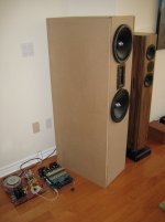
Here is a picture of the prototype box. Since I don't have access to a wood shop anymore, I shamefully got Home Depot to cut the MDF sheets to size and then used industrial strength hot melt glue to hold everything together. You can laugh, but it actually worked incredibly well. I also used the glue gun to make a bead of glue down all the inside joints, which made it air tight and a little stronger.
Attachments

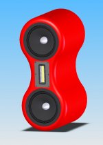
This brings us to the next image, which is the new model I will be sticking with. I drew everything up in Solidworks, with the drivers all modeled as separate parts.
I'll be going with a pearlescent white automotive finish, and the box will probably be either all MDF or alternating layers of MDF and Baltic Birch.
I think I've mentioned the construction process before, but in case I haven't, I'll go over it again here.
I'll be laminating the first two sheets of MDF together here (3/4" each) and then I'll have the front shape of the speakers cut out of it with the driver recesses and everything else on a large CNC. I'll then be using a front to back "Translam" style technique (instead of bottom to top) where I'll simply glue additional layers to the back of the CNC'd front and flush trim them with a 2" spiral up-cut Freud bit to the same shape as the front, two layers at a time.
With enough sanding and diligence, I should be able to get nice clean sides, and do some fancy bracing on the inside of the box. This will also let me make irregular internal surfaces inside the two woofer enclosures. I'll finish the whole thing off with a 1.25" round-over on the front and back, then off to an auto body shop for paint.
This box will be stand mounted initially, and I'll later decide if I want a separate subwoofer to go along with it. The woofer boxes will be sealed as I'm not a very big fan of ported enclosures.
I think the above design will be almost ideal for diffraction, and should at lease be interesting to look at. This is about as close to a spherical enclosure as I can get with the tools I have access to.
Anyone with experience doing automotive finishes on MDF? What do I need to watch for? What primer should be used? Should I let the auto body shop use a high build primer and then sand it? Is laminating in sheets of Baltic Birch asking for trouble?
Measurements to follow!
Attachments
Hi Owen,
If you need some help with cutting the layers let me know. I can do at least an initial baffle on the CNC for you if interested. That would give you the nice template to work from as you are doing the next layers. I think this could be a good option for DIYers in a kit type form. People could rough out the next pieces with a jigsaw and trim as you suggested. It wouldn't be an entry level DIY project but something that some people could definitely pull off. I have 1 1/8" roundover bit as the largest option here right now.
For the painting issue, you really need a good sealer that gets rock hard and doesn't shrink over time. Automotive primers and finishes do not work well. You can have a cabinet nicely finished but after a few days or weeks all of the joints between layers will reappear. I haven't totally found the best option for this yet. Putting a thin layer of fiberglass over the mdf would totally eliminate this issue. I believe this is how Wilson does theirs. There are other sealers I'm looking at from ICA http://www.icaamerica.biz/ Sayerlack http://www.sayerlack.it/ and some other as well. We have a product that is designed for MDF cabinet doors that seals and sands well, but we have to see how it performs on the seams/joints yet.
One thing that could be interesting is to do as well would be stacked layers of baltic birch and then stain and finish. The Evolution MM3 is done this way. http://www.evolutionacoustics.com/mmthree.html
John
2 part clear epoxy is the best I have used to seal wood for an auto paint job. You could also lay a layer of glass in it if you want. I have seen it used with a filler for a nose cone on a kit airplane. Here is a page showing the stuff I use:
http://www.uscomposites.com/epoxy.html
http://www.uscomposites.com/epoxy.html
Hi Guys,
Thanks for the tips! I'll look into some of that epoxy for sealing the finished boxes.
I spent the afternoon playing with an active crossover/eq, and I have some excellent measurements to show for it. I have attached a graph of the full response measured at 1m distance. Nearfield splice at 500Hz, with nearfield data measured from both woofers and the line exit on the back.
I eq'd the bump in the tweeter, and a bump in the woofer at 2500Hz. Crossover is LR4 @ 2000Hz.
The bumps at 110Hz, 360Hz, and 875Hz are ripple caused by the under-stuffed transmission line.
There are also some diffraction related bumps since nothing is flush mounted.
John:
Thanks for the offer to use the CNC! I'm lucky enough to know a guy in town who does it at a good price ($60 for both panels), so it would be cheaper in the long run to have it done here, rather than ship two giant front panels across North America. I appreciate the offer though!
You're right about the kit thing, it would be a great way to sell it. Doing the front baffles is by far the most difficult and time consuming part of making a box, so offering that as a kit would be a big help. All the builder would need is a router, a flush trim bit, a jig saw and some patience.
I was worried about the joints in the MDF cracking the paint over time, and your experience definitely seems to confirm that. Even on speakers I've done veneer work with, you can often see the joints in the MDF after a few years. They appear as little bumps in the veneer.
I guess the clear epoxy is well worth a try, and might be the answer to the problem. I suppose it would have to be applied both inside and out on the cabinet, is that correct Nick?
As for the all Baltic Birch thing, that was my original plan until I worked out the price. Baltic Birch is over 5 times the price of MDF, and a project like this wastes a lot of wood. I figured over $700 in Baltic Birch alone. I suppose I could make a smaller speaker out of the cutouts from the driver holes, but that's a lot of work for something I don't really need.
If I can find a cheaper source for Baltic Birch, I might reconsider. They would certainly be easier to finish if I went that route!
I'll keep everyone posted on the progress with the new box!
Cheers,
Owen
Attachments
Hi Owen,
Have you experimented with your prototype cabinet to create a sealed volume for the Lambda TD10Ms with Qts between ~0.5-0.7 and taken the time to listen to some of your favorite music? You may want to compare sealed midranges with a subwoofer to your rear ported TL prototype. There are many designers who hear superior transients with a sealed midrange plus stuffing to absorb the rear cone wave.
AEspeakers has a new 18" woofer plus their TD15 series, and with speakers a 3-way is not naughty, but it is easy to over-do a good thing.
Regards, and thanks for the interesting data.
Attachments
Hi Linesource,
Testing the sealed TD10M's is next up on my list of things to do. I'm fairly sure I can get away with buying some 12"-13" Sonotube and making some enclosures for both the TD10M's on one of the test baffles I already have.
I do like the sound of TL's but in this case it's a question of size and looks.
What do you use for stuffing in the boxes? Since my enclosures are going to end up being cylindrical, I was thinking something like a Sonic Barrier 1-1/4" on all internal surfaces, followed by Acousta-Stuf for damping, but it has been years since I've done a sealed box, so there's probably something better out there.
The subwoofer will probably be an 18" in a sealed box as well, and I'll use EQ to get it as flat and low as I care to. I have access to some nice 3kW sub amps with DSP based EQ, and I don't mind using that kinda stuff on the bottom end. The mids and highs are another story though.
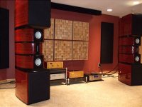
I've seen those speakers around in various "I wish I had these" sorta threads... they're stunning.
What do you use for crossovers and front end? DSP based?
Cheers,
Owen
Testing the sealed TD10M's is next up on my list of things to do. I'm fairly sure I can get away with buying some 12"-13" Sonotube and making some enclosures for both the TD10M's on one of the test baffles I already have.
I do like the sound of TL's but in this case it's a question of size and looks.
What do you use for stuffing in the boxes? Since my enclosures are going to end up being cylindrical, I was thinking something like a Sonic Barrier 1-1/4" on all internal surfaces, followed by Acousta-Stuf for damping, but it has been years since I've done a sealed box, so there's probably something better out there.
The subwoofer will probably be an 18" in a sealed box as well, and I'll use EQ to get it as flat and low as I care to. I have access to some nice 3kW sub amps with DSP based EQ, and I don't mind using that kinda stuff on the bottom end. The mids and highs are another story though.
I've seen those speakers around in various "I wish I had these" sorta threads... they're stunning.
What do you use for crossovers and front end? DSP based?
Cheers,
Owen
I too am keenly interested in seeing how the 10s measure in sealed boxes. I've always thought the sealed units had more "impact", and, were easier to integrate with outboard subs.
Trying to decide whether to do a two way or a three way, with the AE 12s and 6.5s in a three way or the 10s in a two way ... Raal for tweeter in either case, and outboard subs for the very lowest end.
Trying to decide whether to do a two way or a three way, with the AE 12s and 6.5s in a three way or the 10s in a two way ... Raal for tweeter in either case, and outboard subs for the very lowest end.
- Status
- Not open for further replies.
- Home
- Loudspeakers
- Multi-Way
- 10" MTM with NeoPro5i Ribbon - Build Thread