5R1 Mills added to the Coleman reg, it drops exactly 1V, and gives 200mA at 3.4V. C3 is a Musicap, hopefully the leads are not too long, but the 26 is exactly the same.
I changed the Teflons on the gyrator to 0.1uF Audyn True Copper Max caps, but haven't cut the leads at the moment. Will that cause problems?
And I bought a couple of tiny cheap 1A ammeters which I would like to wire in the filament feed, powered from the raw DC for the regs. Would they be likely to cause problems? The sense resistor is 0.05R the unit consumes about 4mA. They would be visible through the gap around the valve bases.
I changed the Teflons on the gyrator to 0.1uF Audyn True Copper Max caps, but haven't cut the leads at the moment. Will that cause problems?
An externally hosted image should be here but it was not working when we last tested it.
And I bought a couple of tiny cheap 1A ammeters which I would like to wire in the filament feed, powered from the raw DC for the regs. Would they be likely to cause problems? The sense resistor is 0.05R the unit consumes about 4mA. They would be visible through the gap around the valve bases.
An externally hosted image should be here but it was not working when we last tested it.
The Mills looks good!
The cap is huge! I would prefer to compare the sound to a smaller physical size. It looks a bit close to the HT, and this might be a risk for pickup. Is it quiet?
Ammeters in the filament circuit are a potential pickup risk (both conducted and radiated), I would not do this. The filament voltage can be checked a few times in the first few hours of runtime, but you should find that after this it will be very stable.
A pity about the ammeter. They're cute! I haven't run the HT yet, so I don't know how it will react. It's the same cap in the 26, but that doesn't have a gyrator.
Great job, well done! Hope it sounds good and you enjoy the 01a!
I just tried a simple upgrade on the CX-112a, easier to adapt. And it sounds really nice:
http://www.bartola.co.uk/valves/2017/03/24/cx-112a-dht-preamp/
Don't want to distract you from your build, but an easy variation to implement if you get hold of the 112a valves!
Cheers
ALe
I just tried a simple upgrade on the CX-112a, easier to adapt. And it sounds really nice:
http://www.bartola.co.uk/valves/2017/03/24/cx-112a-dht-preamp/
Don't want to distract you from your build, but an easy variation to implement if you get hold of the 112a valves!
Cheers
ALe
Get thee behind me Satan! I had enough trouble fighting Andy off when I was building the 26! And look where I am now, building the 01A after all. 
And after it a V25/801.... and so on. 🙂And look where I am now, building the 01A after all.
Wiring finished now (hopefully!), and questions about powering up the HT. In the gyrator, do I start with the pot (P1) wound down anticlockwise? And what resistance can I use as a dummy anode? Va/Ia=Ra? 116/0.003=39k ohms? Or have I got muddled?
I plan to start with the type 26 PSU, just removing the dropper resistor, and see what that gives me.

I plan to start with the type 26 PSU, just removing the dropper resistor, and see what that gives me.
Looking good! I'd rather test them individually. However with any dummy load resistor with 10k or more should do the job instead of the valve.
I'd rather bring ht slowly. If there is anything wrong you will fry the moSfet and the bf862. Which would be a royal pain to replace
I'd rather bring ht slowly. If there is anything wrong you will fry the moSfet and the bf862. Which would be a royal pain to replace
Thanks Ale. I thought Ra was 10-14k, but ohms law gave me 39k! If I use a variac to bring up the HT into a dummy load, without the filament supply connected, that should give me a ballpark setting, no? And do I start with P1 wound down?
Anything above 10K will do the job, the more the less current through the output FETs which could be handy if there is any issue.
As you say, safer with VARIAC and slowly bring HT up. Then you can increase P1 to make sure it sets the voltage you need. If the output voltage is close to HT despite the change in P1, it's a sign of failure of the top MOSFET likely. However, this is unlikely to happen unless you have a short, etc.
Just do some wiring double checks before firing it up.
After a bit of a struggle, I found that 37k (27+10) worked to give me 115V and 3mA at the anode, that's with 204V in. Any lower value either gave me too much current (4mA @27k) or simply wouldn't get the voltage high enough. Will the voltage and current hold up with the actual valve in circuit though?
For the HT supply in the 26 PSU, at the moment I have simply removed the 2k7 resistor from the feed, with no other changes so far.
And the raw DC for the Coleman is 22V, so I added a 27R 20W in line to give me 16.5V, which is about what the 26 has.
My head hurts now, so I may leave it alone until tomorrow.
That's fine. With a 220k reference resistor in the ccs part of the gyrator you won't get too much voltage range. For higher current you need to replace it with a 390k. For the 01a it's fine and you're right a higher dummy load resistor value is needed
All good then, you should be good to test with the 01a 🙂
Hope you like the sound!!
All good then, you should be good to test with the 01a 🙂
Hope you like the sound!!
Yay! As I don't actually know what I'm doing, it's always a pleasant surprise when things work! 
I think I'll leave it for tonight; strong cider and high voltages are not a good combination! Mind you, I used to love soldering when I was tripping, but that was when I was much younger. 😱
I think I'll leave it for tonight; strong cider and high voltages are not a good combination! Mind you, I used to love soldering when I was tripping, but that was when I was much younger. 😱
I fired it up, using the variac for the HT supply, and get 115V at the anodes, and 3.4V across the filaments, so all good so far. Sig gen and scope next.
Well, using the Chinese sig gen I got this! Bloody hell!
So I dragged out the old valve sig gen and got this. 1kHz.
20kHz.
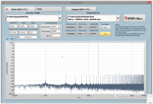
But why is one inverting? Maybe I pressed a button on the scope; I'll have to check that out. The response is 6db down at 120kHz, and just starts to droop at 17kHz, but that's hard to see. And 6dB down at about 8Hz. So not too bad, and I will have to play some music through it next.
This is what it looks like now.
An externally hosted image should be here but it was not working when we last tested it.
So I dragged out the old valve sig gen and got this. 1kHz.
An externally hosted image should be here but it was not working when we last tested it.
20kHz.
An externally hosted image should be here but it was not working when we last tested it.
But why is one inverting? Maybe I pressed a button on the scope; I'll have to check that out. The response is 6db down at 120kHz, and just starts to droop at 17kHz, but that's hard to see. And 6dB down at about 8Hz. So not too bad, and I will have to play some music through it next.
This is what it looks like now.
An externally hosted image should be here but it was not working when we last tested it.
I was referring to one of these things. 2MHz DDS Function Signal Generator Module Sine/Triangle/Square Wave | eBay
It worked fine last time I used it, so I will have a play with it later.
It worked fine last time I used it, so I will have a play with it later.
I checked my scope, and I had pressed the "invert channel 1" button at some point. So the output is inverted, as normal. Phew! Overlaying the input and output traces, the roll-off doesn't really start until 20kHz, and is tiny even then. I still have to finish making the bronze mesh screen clips, and cutting the Sorbothane sheet for the valve dampers, and then I can try it.
It works, but it's incredibly microphonic. And there is some hum, so a bit more work needed. I took off one of the screening cages, but that didn't help, and I have another pair of valves so I will give them a go. And maybe the internal signal wiring will need screening. But the 26 had none of these problems, so I am a little puzzled. But it looks nice so maybe I'll just look at it. 😀
An externally hosted image should be here but it was not working when we last tested it.
- Home
- Amplifiers
- Tubes / Valves
- 01A question