For me the disadvantage of over damped/over filtrated PSU is the output impedance frequency response.
These type (large inductivities with large DCR) circuits commonly has large hump around/under 10Hz, so in general tend to swing if load (amplifier) pull it.
My #26 preamp has simple raw HT supply: AZ1-5uF-10H(100R)-47uF-3H(80R)-220uF.
The hump (about 15Hz) value about 50R, the impedance at 100Hz 7 Ohm.
I use SSHV2 (CCS input), so the load of raw supply is constant (constant current), the impedance peek is irrelevant.
Your original solution has 1.2k peek at -about- 5Hz, 10Hz value 600R, 100Hz value 48R.
This is not problem, if your load -almost constant (for example CCS loaded preamp), but gyrator is dynamic load, the current swing the pace of the music.
At large tutti the current load is pull the PSU, so parasitic swinging would happens.
At least the easy bits are coming along OK. 🙂
An externally hosted image should be here but it was not working when we last tested it.
An externally hosted image should be here but it was not working when we last tested it.
Thanks for the explanation Bela, now I just have try to understand it! 😕For me the disadvantage of over damped/over filtrated PSU is the output impedance frequency response.
These type (large inductivities with large DCR) circuits commonly has large hump around/under 10Hz, so in general tend to swing if load (amplifier) pull it.
My #26 preamp has simple raw HT supply: AZ1-5uF-10H(100R)-47uF-3H(80R)-220uF.
The hump (about 15Hz) value about 50R, the impedance at 100Hz 7 Ohm.
I use SSHV2 (CCS input), so the load of raw supply is constant (constant current), the impedance peek is irrelevant.
Your original solution has 1.2k peek at -about- 5Hz, 10Hz value 600R, 100Hz value 48R.
This is not problem, if your load -almost constant (for example CCS loaded preamp), but gyrator is dynamic load, the current swing the pace of the music.
At large tutti the current load is pull the PSU, so parasitic swinging would happens.
you can just desolder one side of c bypass R1 and see if you like better.....is two min. work !However, this is the PSU I have. I am not going to start removing large parts of it unless it is absolutely essential.
Yes, that is the simple answer I was hoping for, but euro21's explanation of the disadvantages has made me think more about it. And at the moment, with a chest infection, I am struggling to cope with thinking! 🙁you can just desolder one side of c bypass R1 and see if you like better.....is two min. work !
So does the PSU output vary with the music frequency when the load (gyrator) is dynamic? Due to the PSU reactance varying with frequency? Or have I misunderstood?For me the disadvantage of over damped/over filtrated PSU is the output impedance frequency response.
These type (large inductivities with large DCR) circuits commonly has large hump around/under 10Hz, so in general tend to swing if load (amplifier) pull it.
My #26 preamp has simple raw HT supply: AZ1-5uF-10H(100R)-47uF-3H(80R)-220uF.
The hump (about 15Hz) value about 50R, the impedance at 100Hz 7 Ohm.
I use SSHV2 (CCS input), so the load of raw supply is constant (constant current), the impedance peek is irrelevant.
Your original solution has 1.2k peek at -about- 5Hz, 10Hz value 600R, 100Hz value 48R.
This is not problem, if your load -almost constant (for example CCS loaded preamp), but gyrator is dynamic load, the current swing the pace of the music.
At large tutti the current load is pull the PSU, so parasitic swinging would happens.
I seem to have managed to delete some pictures from Photobucket, which deleted them here too. Sorry about that. 
I'm in the middle of transformation of my (5mA CCS loaded, TVC output) #26 preamp to switchable #26/01a.
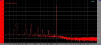
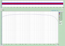
I overcome my laziness and last night put together the most critical parts, the 01a driver.
I use DC coupled SiC FET source follower as driver between 01a (20R filament biased, 5mA CCS loaded 201a) and TVC.
There are the measurements of the driver.
p.s. the bad hum components due to the breadboard wiring.
Attachments
Great work, did you listen to the breadboard stage?
It would be a little difficult, my workshop are in the attic and the whole PSU is about 2 m2. 🙂
In the following week I would put SiC CFs to the #26 preamp, and change the V4 R.C regulator to switchable (01a/#26) V7. The switching also alter between 10R and 20R bias resistor.
My situation is similar. I have my workshop in the attic as well although I ended up building a small test system up there so I can listen to the projects before bringing them down to my listening room.
Attics all round then! I just fired up the Coleman regs (in the attic!) and fed them 13V-20V to see if they would handle my type 26 PSU voltage. They do, but using 3R9 as R1 in the Coleman, I can't get the current below 200mA, although the voltage will change. Is this normal? I don't think I need less than 200mA, but I would like to understand it.
Yes.Is this normal?
The minimal current with 3R9 is -about- 205mA.
Ah, thanks both. I measured 199mA, but my DVM won't be incredibly accurate. Another purchase needed, then.
I don't have a 4R7, but added 1R0 to the 3R9 and tried that. It turns out that I am not fully recovered from my recent illness after all. But I did discover there are several ways to misconnect the power and both DVMs without actually destroying anything! 😱
Anyway, it worked, eventually. I have 200mA at 3.4V again, but can go down to 160mA and 2.6V.
Maybe I should leave the HT until my brain has recovered? 😀
Anyway, it worked, eventually. I have 200mA at 3.4V again, but can go down to 160mA and 2.6V.
Maybe I should leave the HT until my brain has recovered? 😀
My Filament Regulators come with R1 of 3.9Ω for 01A as standard, to support the normal 250mA current level. you can change to any other value of R1, but for best performance (once you are finished testing) set R1 so that it drops 1.0V (0.95 - 1.05V) for preference: this will give the best dc stability and overall performance.
R2 is a resistor-position parallel-connected to R1, to make it easier to get to odd values. So if you decide on a final design current of 200mA, you can use R1=5.1Ω, or R1 = R2 = 10Ω.
R1 and R2 should always be wirewound resistors, over-rated for the power they must burn.
R2 is a resistor-position parallel-connected to R1, to make it easier to get to odd values. So if you decide on a final design current of 200mA, you can use R1=5.1Ω, or R1 = R2 = 10Ω.
R1 and R2 should always be wirewound resistors, over-rated for the power they must burn.
I'll have to order a pair of 5R1 Mills then. I had a Kiwame 5W in there, but a couple of Mills won't break the bank. 🙂
My misfortune temporarily I tried graphite resistor (Mundorf silver) in my #26 preamp R.C. regulator. :-(..but a couple of Mills won't break the bank. 🙂
Now I can buy stockings, before going to bank before withdraw money. 😛pp
- Home
- Amplifiers
- Tubes / Valves
- 01A question