R4 on gyrator is 470 ohms with BF862 JFET per Ale's instructions
Correction R7 or Rmu is 470 ohms and R4 is 390k for the gyrator board I have. Or at least I better check this tonight 🙂
Jim
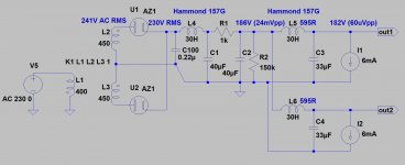
A question, for Ale I guess; this is the HT for my #26, which will be used also for the 01A. Is it OK as it stands? I can easily vary the voltage with R1, but if it will do like this it would make changing over the pre-amps much easier. I wasn't sure how much current the gyrator draws to re-model it PSUD2. And how much voltage headroom does it need? I seem to recall reading 30-40V.
The transformer is a Hammond 370X, 480V CT @ 58mA.
The transformer is a Hammond 370X, 480V CT @ 58mA.
An externally hosted image should be here but it was not working when we last tested it.
how much current the gyrator draws [/IMG]
I= Ianode (at selected operating point) + 0.2 ..... 0.9 mA (LND150 CCS current).
Béla pointed it the current. Don't forget to add additional current drawn by the bleeder resistor as this is a choke input supply. For a 01a preamp running at 3-4mA you will need a bleeder. Also a tunning capacitor is better before the first choke to dial the output voltage like shown here:
http://www.bartola.co.uk/valves/2016/12/23/01a-preamp-gen2-universal-ht-supply/
You need at least 25-30V across the top mosfet to operate properly. Let's say you are biasing the 01a at 115V and the output swings 10V you need at least 115+10+25 = 150V at the input. I'd add some headroom and aim for 180V ( I use 200V). Given the low power of the preamp, there is not much heat dissipated across the top MOSFET which doesn't need a heatsink in this circuit.
Cheers
Ale
Thanks for the info. I just need to try to understand it now! Here is the actual HT supply I have at the moment, changing R1 to 1k sims to about 170V with this layout, assuming 4mA total draw per channel. I1 @20mA is the 15k bleed on the first cap. Would it work? Or do I need another bleed?
I would rather not add a cap at the front if I don't need to, just a switch from the current 2k5 R1 to whatever it needs, 1k probably, to raise the voltage. However if there is an overwhelming reason to change that then of course I will.
I would rather not add a cap at the front if I don't need to, just a switch from the current 2k5 R1 to whatever it needs, 1k probably, to raise the voltage. However if there is an overwhelming reason to change that then of course I will.
An externally hosted image should be here but it was not working when we last tested it.
And I found a couple of 330R Shinkoh tantalums; it seems rude not to use them! 😀
An externally hosted image should be here but it was not working when we last tested it.
IMHO 15k bleeder is waste of current.
I usually put bleeder resistor to the last capacitor (if I use LC smoothing).
My rule thumb is 50k for every 100V.
170V is almost nothing 🙂 (nowadays I develop circuits in the kV region), I usually throw away tongs about 400V. 😛pp
I usually put bleeder resistor to the last capacitor (if I use LC smoothing).
My rule thumb is 50k for every 100V.
170V is almost nothing 🙂 (nowadays I develop circuits in the kV region), I usually throw away tongs about 400V. 😛pp
The minimum current for a choke input supply is Imin(mA)=Vin(RMS)/L(H). You can then subtract 2 times the 01a current (rounded up to 5mA) and the remainder should be what you have to bleed. Put the bleeder after the 40uF capacitor. I'd try to reduce the 2K5 if you can and introduce a tuning capacitor (100-470nF) before the input choke to dial the output voltage. Play with the PSUD2 to obtain the desired output level.
Thanks Ale, I'll give that a go. And do you mean after the 2nd 40uF cap? Or the first, where I have one now?
The last parts should be here soon (valves and Teflon caps), so I had better get it sorted!
The last parts should be here soon (valves and Teflon caps), so I had better get it sorted!
Yes, sorry after the 2nd 40uF cap! Playing with PSUD2 is an enriching experience, you can learn a lot 🙂
Cheers, Ale
Cheers, Ale
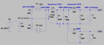
Agreed Béla. I'd remove C2 and R1. Sufficient smoothing is provided by L5/C3 and L6/C4. Having extra 12V won't harm at all.
Voilá.I'd remove C2 and R1.
Attachments
Great stuff. With the 30H input choke the bleeder is only required to discharge the caps and not not guarantee choke input operation. Only important point to highlight is that if the preamp isn't connected by any chance the supply will work as cap-input and maximum HT will be delivered so the caps need to be rated to 500V ideally.
I assume from 40uF and 33uF values, that these capacitors are oil (for example ASC, or GE) or polypropylene types, over the 400V.
If preamp disconnected, the voltage on C1 about 300V.
If preamp disconnected, the voltage on C1 about 300V.
IMHO this PSU is significantly overdamped.
The output "hum" is in the microVolt region.
The gyrator doesn't require this "clearness".
However, this is the PSU I have. I am not going to start removing large parts of it unless it is absolutely essential. But I will try modelling different simple changes. I remember when I was building the 26 (my first attempt at something like this), Andy in particular was trying to persuade me to forget that and go straight to this design. I'm happy I didn't!Agreed Béla. I'd remove C2 and R1. Sufficient smoothing is provided by L5/C3 and L6/C4. Having extra 12V won't harm at all.
The 40uF are ASC oil and the 33uF are Clarity Cap Kelvin polyprops.I assume from 40uF and 33uF values, that these capacitors are oil (for example ASC, or GE) or polypropylene types, over the 400V.
If preamp disconnected, the voltage on C1 about 300V.
BTW, forgive me if I seem to create difficulties, but I struggle with simulations. Even PSUD2! Altering components doesn't seem to work the way I expect. And saving and posting them is even harder! But I guess I could add a switch (or 2) to remove R1 And C2.
- Home
- Amplifiers
- Tubes / Valves
- 01A question